Nissan Murano Z50 (2004 year). Manual - part 176
HEADLAMP -CONVENTIONAL TYPE-
LT-57
C
D
E
F
G
H
I
J
L
M
A
B
LT
Revision: 2004 November
2004 Murano
High Beam Indicator Lamp Does Not Illuminate
AKS00AKI
1.
CHECK BULB
Check bulb of high beam indicator lamp.
OK or NG
OK
>> Replace combination meter.
NG
>> Replace indicator bulb.
Headlamp Low Beam Does Not Illuminate (Both Sides)
AKS00AKJ
1.
CHECK COMBINATION SWITCH INPUT SIGNAL
With CONSULT-II
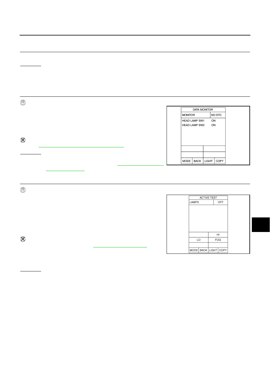
Select “BCM” on CONSULT-II. With “HEAD LAMP” data monitor,
make sure “HEAD LAMP SW 1” and “HEAD LAMP SW 2” turns ON-
OFF linked with operation of lighting switch.
Without CONSULT-II
Refer to
LT-140, "Combination Switch Inspection"
OK or NG
OK
>> GO TO 2.
NG
>> Check lighting switch. Refer to
2.
HEADLAMP ACTIVE TEST
With CONSULT-II
1.
Select “IPDM E/R” on CONSULT-II, and select “ACTIVE TEST”
on “SELECT DIAG MODE” screen.
2.
Select “LAMPS” on “SELECT TEST” ITEM screen.
3.
Touch “LO” screen.
4.
Make sure headlamp low beam operates.
Without CONSULT-II
1.
Start auto active test. Refer to
.
2.
Make sure headlamp low beam operates.
OK or NG
OK
>> GO TO 3.
NG
>> GO TO 4.
When lighting switch is 2ND
position
: HEAD LAMP SW 1 ON
: HEAD LAMP SW 2 ON
PKIA6325E
Headlamp low beam should operate.
Headlamp low beam should operate.
SKIA5774E