Nissan Murano Z50 (2004 year). Manual - part 108
ASCD BRAKE SWITCH
EC-639
C
D
E
F
G
H
I
J
K
L
M
A
EC
Revision: 2004 November
2004 Murano
ASCD BRAKE SWITCH
PFP:25320
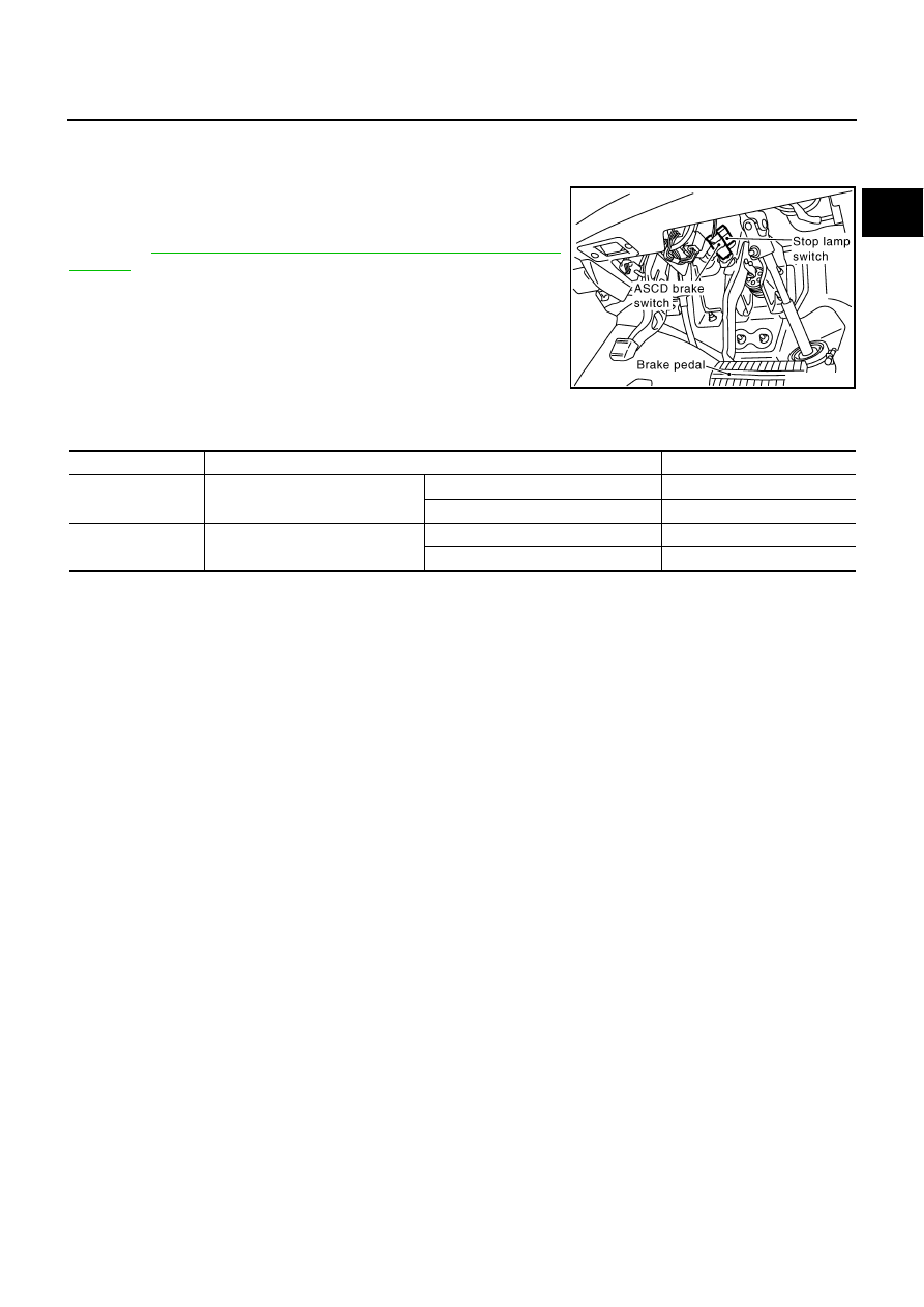
Component Description
ABS004P1
When the brake pedal is depressed, ASCD brake switch is turned
OFF and stop lamp switch is turned ON. ECM detects the state of
the brake pedal by this input of two kinds (ON/OFF signal).
Refer to
EC-665, "AUTOMATIC SPEED CONTROL DEVICE
for the ASCD function.
CONSULT-II Reference Value in Data Monitor Mode
ABS004VT
Specification data are reference values.
PBIB1368E
MONITOR ITEM
CONDITION
SPECIFICATION
BRAKE SW1
●
Ignition switch: ON
Brake pedal: Fully released
ON
Brake pedal: Slightly depressed
OFF
BRAKE SW2
●
Ignition switch: ON
Brake pedal: Fully released
OFF
Brake pedal: Slightly depressed
ON