Nissan Murano Z50 (2003 year). Manual - part 240
LT-328
INTERIOR ROOM LAMP
Revision; 2004 April
2003 Murano
3.
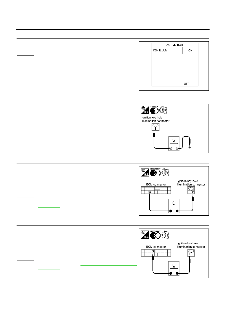
ACTIVE TEST
1.
Select “BCM” on CONSULT-II. Select “INT LAMP”.
2.
Select “IGN ILLUM” active test to make sure lamp operates.
OK or NG
OK
BCS-36, "Removal and Installa-
NG
>> GO TO 4.
4.
CHECK IGNITION KEY HOLE ILLUMINATION INPUT
1.
Turn ignition switch OFF.
2.
Check voltage between ignition key hole illumination harness
connector M40 terminal 1 (P) and ground.
OK or NG
OK
>> GO TO 5.
NG
>> GO TO 6.
5.
CHECK IGNITION KEY HOLE ILLUMINATION CIRCUIT
1.
Disconnect BCM connector and key hole illumination connector.
2.
Check continuity between BCM harness connector M35 terminal
34 (R/Y) and key hole illumination harness connector M40 termi-
nal 2 (R/Y).
OK or NG
OK
>> Replace BCM. Refer to
BCS-36, "Removal and Installa-
NG
>> Repair harness or connector.
6.
CHECK IGNITION KEY HOLE ILLUMINATION CIRCUIT
1.
Disconnect BCM connector and key hole illumination connector.
2.
Check continuity between BCM harness connector M35 terminal
24 (P) and key hole illumination harness connector M40 terminal
1 (P).
OK or NG
OK
>> Replace BCM. Refer to
BCS-36, "Removal and Installa-
NG
>> Repair harness or connector.
SKIA3992E
Battery voltage should exist.
SKIA4563E
Continuity should exist.
SKIA4564E
Continuity should exist.
SKIA4565E