Index Manuals Nissan Murano Z50 (2003 year) - Service and Repair Manual
Search copyright infringement
Content .. 236 237 238 239 ..
Nissan Murano Z50 (2003 year). Manual - part 238
LT-296
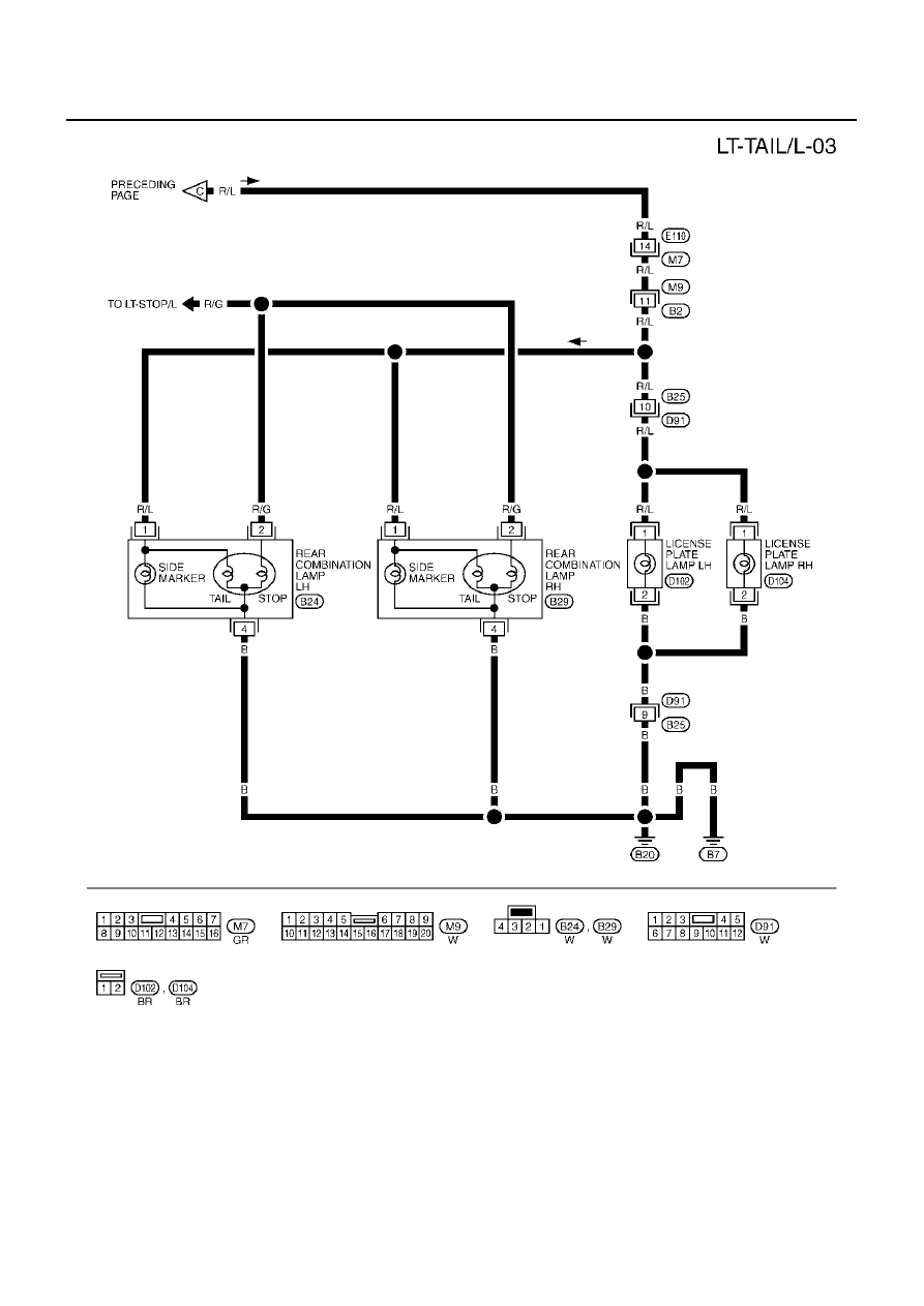
PARKING, LICENSE PLATE AND TAIL LAMPS
Revision; 2004 April
2003 Murano
TKWA0774E