Nissan Murano Z50 (2003 year). Manual - part 201
LAN-830
[CAN]
CAN SYSTEM (TYPE 24)
Revision; 2004 April
2003 Murano
2.
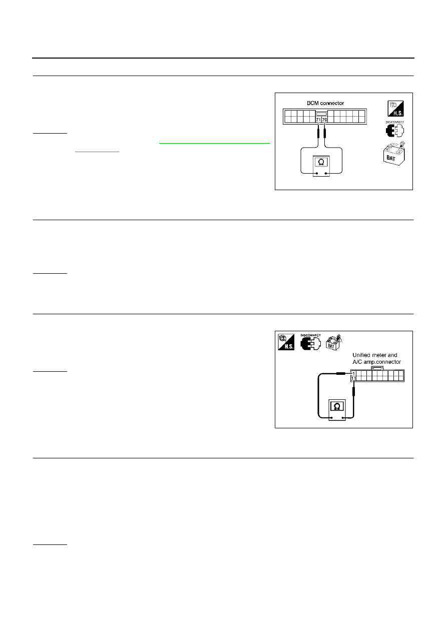
CHECK HARNESS FOR OPEN CIRCUIT
1.
Disconnect BCM connector.
2.
Check resistance between BCM harness connector M37 termi-
nals 70 (L) and 71 (Y).
OK or NG
OK
>> Replace BCM. Refer to
BCS-36, "Removal and Installa-
NG
>> Repair harness between BCM and data link connector.
Unified Meter and A/C Amp. Circuit Check
AKS00744
1.
CHECK CONNECTOR
1.
Turn ignition switch OFF.
2.
Disconnect the negative battery terminal.
3.
Check terminals and connector of unified meter and A/C amp. for damage, bend and loose connection
(meter side and harness side).
OK or NG
OK
>> GO TO 2.
NG
>> Repair terminal or connector.
2.
CHECK HARNESS FOR OPEN CIRCUIT
1.
Disconnect unified meter and A/C amp. connector.
2.
Check resistance between unified meter and A/C amp. harness
connector M49 terminals 1 (L) and 11 (Y).
OK or NG
OK
>> Replace unified meter and A/C amp.
NG
>> Repair harness between unified meter and A/C amp.
and data link connector.
Driver Seat Control Unit Circuit Check
AKS00745
1.
CHECK CONNECTOR
1.
Turn ignition switch OFF.
2.
Disconnect the negative battery terminal.
3.
Check following terminals and connectors for damage, bend and loose connection (control unit side and
harness side).
●
Driver seat control unit connector
●
Harness connector B301
●
Harness connector B9
OK or NG
OK
>> GO TO 2.
NG
>> Repair terminal or connector.
70 (L) - 71 (Y)
: Approx. 54 - 66
Ω
LKIA0028E
1 (L) - 11 (Y)
: Approx. 54 - 66
Ω
PKIA2078E