Nissan Murano Z50 (2003 year). Manual - part 136


  Index      Manuals     Nissan Murano Z50 (2003 year) - Service and Repair Manual


Search            copyright infringement  


Content      ..     134      135      136      137     ..


Nissan Murano Z50 (2003 year). Manual - part 136


COIL SPRING AND STRUT

FSU-9

C

D

F

G

H

I

J

K

L

M

A

B

FSU

Revision; 2004 April

2003 Murano

COIL SPRING AND STRUT

PFP:55302

Removal and Installation

AES000NM

REMOVAL

1.

Remove tire with power tool.

2.

Remove cowl top grille. Refer to 

EI-21, "COWL TOP"

 .

3.

Remove brake caliper with power tool. Hang it in a place where it will not interfere with work. Refer to 

BR-

28, "Removal and Installation of Brake Caliper Assembly"

 .

4.

Remove lock plate of brake hose from strut assembly.

5.

Remove harness of wheel sensor from strut assembly. Refer to 

BRC-64, "WHEEL SENSORS"

 .

NOTE:
Do not pull on wheel sensor harness.

6.

Remove mounting nut between strut assembly and connecting rod.

7.

Remove mounting bolt and nut between strut assembly and steering knuckle with power tool.

8.

Remove mounting nuts on mounting insulator bracket with power tool, then remove strut assembly from
vehicle.

INSTALLATION

Refer to 

FSU-7, "Components"

  for tightening torque. Install in the reverse order of removal.

NOTE:
Refer to component parts location and do not reuse non-reusable parts.

Perform final tightening of strut assembly lower side (rubber bushing) under unladen conditions with tires
on level ground. Check wheel alignment. Refer to 

FSU-16, "SERVICE DATA AND SPECIFICATIONS

(SDS)"

 .

Disassembly and Assembly

AES000NN

DISASSEMBLY

NOTE:
Make sure piston rod on strut is not damaged when removing components from strut assembly.
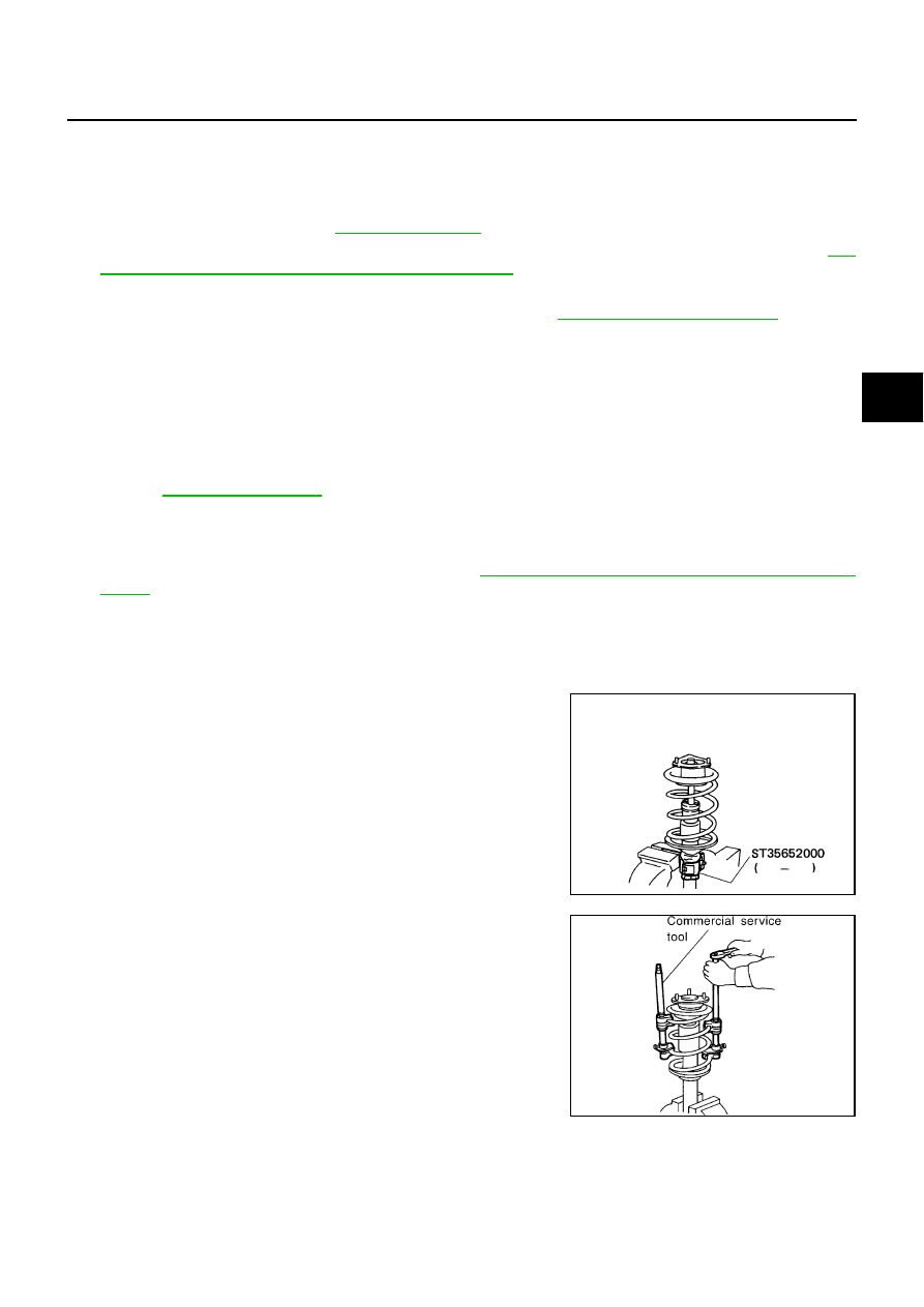
1.

Install strut attachment (SST) to strut and fix it in a vise.

CAUTION:

When installing strut attachment (SST) to strut, wrap a shop
cloth around strut to protect it from damage.

2.

Using a spring compressor (commercial service tool), compress
coil spring between spring upper seat and spring lower seat (on
strut) until coil spring is free.

CAUTION:

Be sure spring compressor (commercial service tool) is
securely attached to coil spring. Compress coil spring.

SEIA0296E

SEIA0297E

FSU-10

COIL SPRING AND STRUT

Revision; 2004 April

2003 Murano

3.

Make sure coil spring between spring upper seat and spring
lower seat is free and then secure piston rod tip so that piston
rod does not turn, and remove piston rod lock nut.

4.

Remove upper mounting plate, mounting insulator, mounting insulator bracket, mounting bearing, spring
upper rubber seat coil spring, spring lower rubber seat from strut.

5.

Gradually release spring compressor (commercial service tool), and remove coil spring.

CAUTION:

Loosen while making sure coil spring attachment position does not move.

6.

Remove bound bumper from spring upper seat.

7.

Remove strut attachment (special service tool) from strut.

INSPECTION AFTER DISASSEMBLY
Strut Inspection

Check strut for deformation, cracks or damage, and replace if necessary.

Check piston rod for damage, uneven wear or distortion, and replace if necessary.

Check welded and sealed areas for oil leakage, and replace if necessary.

Mounting Insulator and Rubber Parts Inspection

Check mounting insulator for cracks and rubber parts for wear. Replace them if necessary.

Coil Spring Inspection

Check coil spring for cracks, wear or damage, and replace if necessary.

ASSEMBLY

NOTE:
Make sure piston rod on strut is not damaged when attaching components to strut.
1.

Install strut attachment (SST) to strut and fix it in a vise.

CAUTION:

When installing strut attachment (SST) to strut, wrap a shop cloth around strut to protect it from
damage.

2.

Install spring lower seat to strut.

3.

Compress coil spring using a spring compressor (commercial service tool), and install it onto strut.

CAUTION:

Face tube side of coil spring downward. Align lower end
to spring rubber seat as shown in the figure.

Be sure spring compressor (commercial service tool) is
securely attached to coil spring. Compress coil spring.

4.

Install bound bumper to spring upper seat.

SEIA0218J

SFA149

COIL SPRING AND STRUT

FSU-11

C

D

F

G

H

I

J

K

L

M

A

B

FSU

Revision; 2004 April

2003 Murano

5.

Install spring upper rubber seat, spring upper seat, mounting
bearing, mounting insulator bracket, mounting insulator, upper
mounting plate.

Installation position of spring upper seat is as shown in the fig-
ure.

6.

Fix strut mounting insulator, then tighten piston rod lock nut with
specified torque.

CAUTION:

Be careful not do deform mounting insulator bracket.

7.

Gradually release spring compressor (commercial service tool), and remove coil spring.

CAUTION:

Loosen while making sure coil spring attachment position does not move.

8.

Remove strut attachment (SST) from strut.

SEIA0247E

SEIA0298E

FSU-12

TRANSVERSE LINK

Revision; 2004 April

2003 Murano

TRANSVERSE LINK

PFP:54500

Removal and Installation

AES000GH

REMOVAL

1.

Remove tire with power tool.

2.

Remove mounting bolt between transverse link and front suspension member with power tool.

3.

Remove transverse link from steering knuckle. Refer to 

FAX-5, "FRONT WHEEL HUB AND KNUCKLE"

4.

Remove transverse link from vehicle.

INSPECTION AFTER REMOVAL
Visual Inspection

Check transverse link and bushing for deformation, cracks, or damage. If any non-standard condition is
found, replace it.

Check boot of ball joint for cracks or other damage, and also for grease leakage. If any non-standard con-
dition is found, replace it.

Ball Joint Inspection

Manually move ball stud to confirm it moves smoothly with no binding.

Swing Torque Inspection

NOTE:
Before measurement, move ball joint at least ten times by hand to check for smooth movement.

Hook spring scale at ball stud. Confirm spring scale measure-
ment value is within specifications when ball stud begins mov-
ing.

If it is outside the specified range, replace suspension arm
assembly.

Rotating Torque Inspection

Attach mounting nut to ball stud. Check that sliding torque is
within specifications with a preload gauge (SST).

If it is outside the specified range, replace suspension arm
assembly.

Axial End Play Inspection

Move tip of ball joint in axial direction to check for looseness.

If it is outside the specified range, replace suspension arm assembly.

INSTALLATION

Refer to 

FSU-7, "Components"

  for tightening torque. Install in the reverse order of removal.

NOTE:
Refer to component parts location and do not reuse non-reusable parts.

Swing torque:

0.5 - 3.4 N·m (0.06 - 0.34 kg-m, 5 - 30 in-lb)

Measure value of spring scale:

13.5 - 91.9 N (1.4 - 9.3 kg, 3.08 - 20.5 lb)

SDIA1143E

Rotating torque:

0.5 - 3.4 N·m (0.06 - 0.34 kg-m, 5 - 30 in-lb)

SDIA1150E

Axial end play

: 0 mm (0 in)

TRANSVERSE LINK

FSU-13

C

D

F

G

H

I

J

K

L

M

A

B

FSU

Revision; 2004 April

2003 Murano

Perform final tightening of front suspension member installation position and strut assembly lower side
(rubber bushing) under unladen conditions with tires on level ground. Check wheel alignment. Refer to

FSU-5, "Wheel Alignment Inspection"

 .

FSU-14

STABILIZER BAR

Revision; 2004 April

2003 Murano

STABILIZER BAR

PFP:54611

Removal and Installation

AES000GK

REMOVAL
2WD

1.

Remove tire with power tool.

2.

Remove steering gear assembly from vehicle. Refer to 

PS-14, "POWER STEERING GEAR AND LINK-

AGE"

 .

3.

Remove stabilizer connecting rod lower nut, separate stabilizer bar and stabilizer connecting rod with
power tool.

4.

Remove stabilizer clamp mounting bolts with power tool.

5.

Remove stabilizer bar from vehicle.

AWD

1.

Remove steering gear assembly. Refer to 

PS-14, "REMOVAL"

 .

2.

Remove stabilizer bar from vehicle.

INSPECTION AFTER REMOVAL

Check stabilizer bar, stabilizer connecting rod, stabilizer bushing and stabilizer clamp for deformation, cracks
or damage, and replace if necessary.

INSTALLATION

Refer to 

FSU-7, "Components"

  for tightening torque. Install in the reverse order of removal.

NOTE:
Refer to component parts location and do not reuse non-reusable parts.

Tighten bolts for tightening stabilizer clamp. Tightening order is front LH, rear RH, front RH, rear LH.

Stabilizer bar uses pillow ball type connecting rod. Position ball
joint with case on pillow ball head parallel to stabilizer bar.

SFA449BB

FRONT SUSPENSION MEMBER

FSU-15

C

D

F

G

H

I

J

K

L

M

A

B

FSU

Revision; 2004 April

2003 Murano

FRONT SUSPENSION MEMBER

PFP:54401

Removal and Installation

AES000GL

REMOVAL

Remove suspension member with engine assembly from vehicle. Refer to “ENGINE MECHANICAL” section

EM-95, "ENGINE ASSEMBLY"

 .

INSPECTION AFTER REMOVAL

Check front suspension member for deformation, cracks, or any other damage. Replace if necessary.

INSTALLATION

Install in the reverse order of removal.

Perform final tightening of installation position between front suspension member and transverse link (rub-
ber bushing) under unladen conditions with tires on level ground. Check wheel alignment. Refer to 

FSU-5,

"Wheel Alignment Inspection"

 .

FSU-16

SERVICE DATA AND SPECIFICATIONS (SDS)

Revision; 2004 April

2003 Murano

SERVICE DATA AND SPECIFICATIONS (SDS)

PFP:00030

Wheel Alignment (Unladen)

AES000NG

Ball Joint

AES000NH

Wheelarch Height (Unladen*)

AES000NI

*: Fuel, radiator coolant and engine oil full. Spare tire, jack, hand tools and mats are in designated positions.

Camber
Degree minute (Decimal degree)

Minimum

– 1

°

 05

 (– 1.08

°

)

Nominal

– 0

°

 20

 (– 0.33

°

)

Maximum

0

°

 25

 (0.41

°

)

Left and right difference

45

 (0.75

°

) or less

Caster
Degree minute (Decimal degree)

Minimum

1

°

 50

 (1.83

°

)

Nominal

2

°

 35

 (2.58

°

)

Maximum

3

°

 20

 (3.33

°

)

Left and right difference

45

 (0.75

°

) or less

Kingpin inclination
Degree minute (Decimal degree)

Minimum

13

°

 35

 (13.58

°

)

Nominal

14

°

 20

 (14.33

°

)

Maximum

15

°

 05

 (15.08

°

)

Total toe-in

Distance (A - B)

Minimum

– 0.5 mm (– 0.02 in)

Nominal

0.5 mm (0.02 in)

Maximum

1.5 mm (0.06 in)

Angle (left plus right)
Degree minute (Degree)

Minimum

– 1

 (– 0.02

°

)

Nominal

1

 (0.02

°

)

Maximum

3

 (0.05

°

)

Axial end play

0 mm (0 in)

Swing torque

0.5 - 3.4 N·m (0.06 - 0.34 kg-m, 5 - 30 in-lb)

Measurement on spring balance

13.5 - 91.9 N (1.4 - 9.3 kg-m, 3.08 - 20.5 lb)

Rotating torque

0.5 - 3.4 N·m (0.06 - 0.34 kg-m, 5 - 30 in-lb)

Applied model

235/65R18

Grade

Except SE

SE

Front (Hf)

840 mm (33.07 in)

839 mm (33.03 in)

Rear (Hr)

858 mm (33.78 in)

857 mm (33.74 in)

SFA818A

A
B
C
D

E

F

G

H

I

J

K

M

L

QUICK REFERENCE INDEX


A GENERAL INFORMATION

GI

General Information

B ENGINE

EM

Engine Mechanical

LU

Engine Lubrication System

CO

Engine Cooling System

EC

Engine Control System

FL

Fuel System

EX

Exhaust System

ACC

Accelerator Control System

C TRANSMISSION/

TRANSAXLE

CVT

CVT

D DRIVELINE/AXLE

TF

Transfer

PR

Propeller Shaft

RFD

Rear Final Drive

FAX

Front Axle

RAX

Rear Axle

E SUSPENSION

FSU

Front Suspension

RSU

Rear Suspension

WT

Road Wheels & Tires

F BRAKES

BR

Brake System

PB

Parking Brake System

BRC

Brake Control System

G STEERING

PS

Power Steering System

H RESTRAINTS

SB

Seat Belts

SRS

Supplemental Restraint System 
(SRS)

I BODY

BL

Body, Lock & Security System

GW

Glasses, Window System & Mir-
rors

RF

Roof

EI

Exterior & Interior

IP

Instrument Panel

SE

Seat

AP

Adjustable Pedal

J AIR CONDITIONER

ATC

Automatic Air Conditioner

K ELECTRICAL

SC

Starting & Charging System

LT

Lighting System

DI

Driver Information System

WW

Wiper, Washer & Horn

BCS

Body Control System

LAN

LAN System

AV

Audio, Visual,Navigation & Tele-
phone System

ACS

Auto Cruise Control System

PG

Power Supply, Ground & Circuit Ele-
ments

L MAINTENANCE

MA

Maintenance

M INDEX

IDX

Alphabetical Index

All rights reserved. No part of this Service Manual may be reproduced or stored in a retrieval system, or 
transmitted in any form, or by any means, electronic, mechanical, recording or otherwise, without the prior 
written permission of Nissan Motor Company Ltd., Tokyo, Japan.

Edition: November 2002
Revision: April 2004
Publication No. SM3E-1Z50U4

FOREWORD

This manual contains maintenance and repair procedure for the 2003
NISSAN MURANO.

In order to assure your safety and the efficient functioning of the vehicle, 
this manual should be read thoroughly. It is especially important that the 
PRECAUTIONS in the GI section be completely understood before starting 
any repair task. 

All information in this manual is based on the latest product information
at the time of publication. The right is reserved to make changes in specifi-
cations and methods at any time without notice.

IMPORTANT SAFETY NOTICE

The proper performance of service is essential for both the safety of
the technician and the efficient functioning of the vehicle.
The service methods in this Service Manual are described in such a
manner that the service may be performed safely and accurately.
Service varies with the procedures used, the skills of the technician
and the tools and parts available. Accordingly, anyone using service
procedures, tools or parts which are not specifically recommended
by NISSAN must first be completely satisfied that neither personal
safety nor the vehicle’s safety will be jeopardized by the service
method selected.

PLEASE HELP MAKE THIS SERVICE MANUAL BETTER!

Your comments are important to NISSAN and will help us to improve our Service Manuals.
Use this form to report any issues or comments you may have regarding our Service Manuals.
Please print this form and type or write your comments below. Mail or fax to:

Nissan North America, Inc.
Technical Service Information
39001 Sunrise Drive, P.O. Box 9200
Farmington Hills, MI USA 48331
FAX: (248) 488-3910

SERVICE MANUAL: Model:

Year:

PUBLICATION NO. (Refer to Quick Reference Index ):

Please describe any Service Manual issues or problems in detail:
Page number(s)

Note: Please include a copy of each page, marked with your comments.

Are the trouble diagnosis procedures logical and easy to use? (circle your answer)

YES

NO

If no, what page number(s)?

Note: Please include a copy of each page, marked with your comments.

Please describe the issue or problem in detail:

Is the organization of the manual clear and easy to follow? (circle your answer)

YES

NO

Please comment:

What information should be included in NISSAN Service Manuals to better support you in servicing or
repairing customer vehicles?

DATE:

YOUR NAME:

POSITION:

DEALER:

DEALER NO.:

ADDRESS:

CITY:

STATE/PROV./COUNTRY:

ZIP/POSTAL CODE:

INCH TO METRIC CONVERSION TABLE

(Rounded-off for automotive use)

inches

mm

inches

mm

.100

2.54

.610

15.49

.110

2.79

.620

15.75

.120

3.05

.630

16.00

.130

3.30

.640

16.26

.140

3.56

.650

16.51

.150

3.81

.660

16.76

.160

4.06

.670

17.02

.170

4.32

.680

17.27

.180

4.57

.690

17.53

.190

4.83

.700

17.78

.200

5.08

.710

18.03

.210

5.33

.720

18.29

.220

5.59

.730

18.54

.230

5.84

.740

18.80

.240

6.10

.750

19.05

.250

6.35

.760

19.30

.260

6.60

.770

19.56

.270

6.86

.780

19.81

.280

7.11

.790

20.07

.290

7.37

.800

20.32

.300

7.62

.810

20.57

.310

7.87

.820

20.83

.320

8.13

.830

21.08

.330

8.38

.840

21.34

.340

8.64

.850

21.59

.350

8.89

.860

21.84

.360

9.14

.870

22.10

.370

9.40

.880

22.35

.380

9.65

.890

22.61

.390

9.91

.900

22.86

.400

10.16

.910

23.11

.410

10.41

.920

23.37

.420

10.67

.930

23.62

.430

10.92

.940

23.88

.440

11.18

.950

24.13

.450

11.43

.960

24.38

.460

11.68

.970

24.64

.470

11.94

.980

24.89

.480

12.19

.990

25.15

.490

12.45

1.000

25.40

.500

12.70

2.000

50.80

.510

12.95

3.000

76.20

.520

13.21

4.000

101.60

.530

13.46

5.000

127.00

.540

13.72

6.000

152.40

.550

13.97

7.000

177.80

.560

14.22

8.000

203.20

.570

14.48

9.000

228.60

.580

14.73

10.000

254.00

.590

14.99

20.000

508.00

.600

15.24

METRIC TO INCH CONVERSION TABLE

(Rounded-off for automotive use)

mm

inches

mm

inches

1

.0394

51

2.008

2

.079

52

2.047

3

.118

53

2.087

4

.157

54

2.126

5

.197

55

2.165

6

.236

56

2.205

7

.276

57

2.244

8

.315

58

2.283

9

.354

59

2.323

10

.394

60

2.362

11

.433

61

2.402

12

.472

62

2.441

13

.512

63

2.480

14

.551

64

2.520

15

.591

65

2.559

16

.630

66

2.598

17

.669

67

2.638

18

.709

68

2.677

19

.748

69

2.717

20

.787

70

2.756

21

.827

71

2.795

22

.866

72

2.835

23

.906

73

2.874

24

.945

74

2.913

25

.984

75

2.953

26

1.024

76

2.992

27

1.063

77

3.031

28

1.102

78

3.071

29

1.142

79

3.110

30

1.181

80

3.150

31

1.220

81

3.189

32

1.260

82

3.228

33

1.299

83

3.268

34

1.339

84

3.307

35

1.378

85

3.346

36

1.417

86

3.386

37

1.457

87

3.425

38

1.496

88

3.465

39

1.535

89

3.504

40

1.575

90

3.543

41

1.614

91

3.583

42

1.654

92

3.622

43

1.693

93

3.661

44

1.732

94

3.701

45

1.772

95

3.740

46

1.811

96

3.780

47

1.850

97

3.819

48

1.890

98

3.858

49

1.929

99

3.898

50

1.969

100

3.937

QUICK REFERENCE CHART MURANO

QUICK REFERENCE CHART MURANO

PFP:00000

ENGINE TUNE-UP DATA (VQ35DE)

ELS0003W

Engine  model

VQ35DE

Firing order

1-2-3-4-5-6

Idle speed
CVT (In “P” or “N” position)

rpm

650±50

Ignition timing (BTDC at idle speed)
CVT (In “P” or “N” position)

15

°

± 5

°

CO%  at  idle 

0.7 - 9.9 % and engine runs smoothly

Drive Belt

Deflection adjustment                              Unit: mm (in)

Tension adjustment                          Unit: N (kg, lb)

Used belt

New belt

Used belt

New belt

Limit

After adjustment

Limit

 After adjustment

Alternator and air condi-
tioner compressor belt

7 (0.28)

4.2 - 4.6

(0.17 - 0.18)

3.7 - 4.1

(0.15 - 0.16)

294 (30, 66)

730 - 818

(74.5 - 83.5,

164 - 184)

838 - 926

(85.5 - 94.5,

188 - 208)

Power steering oil pump 
belt

11 (0.43)

7.3 - 8

(0.29 - 0.30)

6.5 - 7.2

(0.26- 0.28)

196 (20, 44)

495 - 583

(50.5 - 59.5,

111 - 131)

603 - 691

(61.5  -  70.5,         

135.6 - 155.4)

Applied pushing force

98N (10kg, 22lb)

 —

Radiater cap relief pressure

kPa (kg/cm

2

 , psi)

78 - 98 (0.8 - 1.0, 11 - 14)

Standard

Limit

59 (0.6, 9)

Cooling system leakage testing pres-
sure

kPa (kg/cm

2

 , psi)

157(1.6, 23)

Compression pressure

kPa (kg/cm

2

 , psi)/rpm

1,275 (13.0, 185) /300

Standard

Minimum

981 (10.0, 142)/300

Spark plug

Make

NGK

Standard type

PLFR5A - 11

Hot type

PLFR4A - 11

Cold type

PLFR6A - 11

Gap (Nominal)                       mm(in)

1.1 ( 0.043 )

2003

QUICK REFERENCE CHART MURANO

FRONT WHEEL ALIGNMENT (Unladen* )

ELS0003X

* : Fuel, engine coolant and engine oil full.   Spare tire, jack, hand tools and mats in designated positions.

REAR WHEEL ALIGNMENT (Unladen*)

ELS0003Y

* : Fuel, engine coolant and engine oil full.   Spare tire, jack, hand tools and mats in designated positions.

BRAKE

ELS0003Z

* : Under force of 490 N( 50 kg, 110 lb ) with engine running.

Camber

Degree minute (Decimal degree)

Minimum

– 1

°

 05

 ( – 1.08

°

 )

Nominal

– 0

°

 20

 ( – 0.33

°

 )

Maximum

 0

°

 25

 ( 0.41

°

 )

Left and right difference

45

 ( 0.75

°

 ) or less

Caster

Degree minute (Decimal degree)

Minimum

1

°

 50

 ( 1.83

°

 )

Nominal

2

°

 35

 ( 2.58

°

 )

Maximum

3

°

 20

 ( 3.33

°

 )

Left and right difference

45

 ( 0.75

°

 ) or less

Kingpin inclination

Degree minute (Decimal degree)

Minimum

13

°

 35

 ( 13.58

°

 )

Nominal

14

°

 20

 ( 14.33

°

 )

Maximum

15

°

 05

 ( 15.08

°

 )

Total toe-in

Distance (A – B)

Minimum

– 0.5 mm ( – 0.02 in )

Nominal

0.5 mm ( 0.02 in )

Maximum

1.5 mm ( 0.06 in )

Angle (left plus right)

Degree minute (Degree)

Minimum

– 1

 ( – 0.02

°

 )

Nominal

 1

 ( 0.02

°

 )

Maximum

3

 ( 0.05

°

 )

Wheel turning angle (Full turn)

Inside

MInimum

35

°

 00

 ( 35.0

°

 )

Degree minute (Decimal degree)

Nominal

38

°

 00

 ( 38.0

°

 )

Maximum

39

°

 00

 ( 39.0

°

 )

Outside

Nominal

31

°

 30

 ( 31.5

°

 )

Degree minute (Decimal degree)

Grade

Except SE

SE

Camber
Degree minute (Decimal degree)

Minimum

– 1

°

 16

 ( – 1.27

°


)

–  1

°

 18

 ( – 1.30

°

 )

Nominal

– 0

°

 46

 ( – 0.77

°


)

–  0

°

 48

 ( – 0.80

°

 )

Maximum

– 0

°

 16

 ( – 0.27

°


)

–  0

°

 18

 ( – 0.30

°

 )

Total toe-in

Distance ( A – B )

Minimum

1.4 mm ( 0.055 in ) 

1.7 mm ( 0.067 in )

Nominal

3.2 mm ( 0.126 in ) 

3.5 mm ( 0.138 in )

Maximum

5.0 mm ( 0.197 in ) 

5.3 mm ( 0.209 in )

Angle (left plus right )

Degree minute (Degree)

Minimum

3

 ( 0.05

°


)

4

 ( 0.07

°

 )

Nominal

7

 ( 0.12

°


)

8

 ( 0.13

°

 )

Maximum

11

 ( 0.18

°


)

12

 ( 0.20

°

 )

Front brake

Pad wear limit

2.0 ( 0.079 )

Rotor repair limit

26.0 mm ( 1.024 in )

Rear brake

Pad wear limit

2.0 mm ( 0.079 in )

Rotor repair limit

14.0 mm ( 0.551 in )

Pedal free height

199.5 - 209.5 mm ( 7.85 - 8.25 in )

Pedal depressed height*

120 mm ( 4.72 in )

2003

QUICK REFERENCE CHART MURANO

REFILL CAPACITIES

ELS00040

UNIT

Liter

US measure

Fuel tank

82

21 - 5/8 gal

Coolant ( With reservoir tank )

9.2

9 - 3/4 qt

Engine

Drain and refill

With oil filter change

4.0

4 - 1/4 qt

Without oil filter change

3.7

3 - 7/8 qt

Dry engine (Overhaul)

5.0

5 - 1/4 qt

Transmission

CVT

10.2

10 - 6/8 qt

Transfer

0.310

5/8 pt

Differential carrier

0.55

1 - 1/8 pt

Power steering system

1.0

1 - 1/8 qt

Air conditioning system

Compressor oil

0.15

5.03 fl oz

Refrigerant

0.55 kg

1.21 lb

2003

Attachment No.35


TID

CID

P0420

01H

01H

Max.

1/128

P0420

02H

81H

Min.

1

P0430

03H

02H

Max.

1/128

P0430

04H

82H

Min.

1

EVAP control system (Small leak)

P0442

05H

03H

Max.

1/128mm

2

EVAP control system purge flow monitoring

P0441

06H

83H

Min.

20mV

EVAP control system (Very small leak)

P0456

07H

03H

Max.

1/128mm

2

P0133

09H

04H

Max.

16ms

P1143

0AH

84H

Min.

10mV

P1144

0BH

04H

Max.

10mV

P0132

0CH

04H

Max.

10mV

P0134

0DH

04H

Max.

1s

P0153

11H

05H

Max.

16ms

P1163

12H

85H

Min.

10mV

P1164

13H

05H

Max.

10mV

P0152

14H

05H

Max.

10mV

P0154

15H

05H

Max.

1s

P0139

19H

86H

Min.

10mV/500ms

P1147

1AH

86H

Min.

10mV

P1146

1BH

06H

Max.

10mV

P0138

1CH

06H

Max.

10mV

P0159

21H

87H

Min.

10mV/500ms

P1167

22H

87H

Min.

10mV

P1166

23H

07H

Max.

10mV

P0158

24H

07H

Max.

10mV

P0032

29H

08H

Max.

20mV

P0031

2AH

88H

Min.

20mV

P0052

2BH

09H

Max.

20mV

P0051

2CH

89H

Min.

20mV

P0038

2DH

0AH

Max.

20mV

P0037

2EH

8AH

Min.

20mV

P0058

2FH

0BH

Max.

20mV

P0057

30H

8BH

Min.

20mV

HO2S HTR

Heated oxygen sensor 1 heater (Bank 1)

Heated oxygen sensor 1 heater (Bank 2)

Heated oxygen sensor 2 heater (Bank 1)

Heated oxygen sensor 2 heater (Bank 2)

EVAP SYSTEM

HO2S

Heated oxygen sensor 1 (Bank 1)

Heated oxygen sensor 1 (Bank 2)

Heated oxygen sensor 2 (Bank 1)

Heated oxygen sensor 2 (Bank 2)

CATALYST

Three way catalyst function (Bank 1)

Three way catalyst function (Bank 2)

SRT item 

Self-diagnostic test item

maximum or minimum value and is compared with the test value being monitored.
These data (test value and test limit) are specified by Test ID (TID) and Component ID (CID) and can be dis-
played on the GST screen.

Test limit

Conversion

DTC

Test value

 (GST display)

TEST VALUE AND TEST LIMIT (GST ONLY — NOT APPLICABLE TO CONSULT-II)

The following is the information specified in Mode 6 of SAE J1979.
The test value is a parameter used to determine whether a system/circuit diagnostic test is “OK” or “NG” while
being monitored by the ECM during self-diagnosis. The test limit is a reference value which is specified as the


Content      ..     134      135      136      137     ..