Nissan Murano Z50 (2003 year). Manual - part 135


  Index      Manuals     Nissan Murano Z50 (2003 year) - Service and Repair Manual


Search            copyright infringement  


Content      ..     133      134      135      136     ..


Nissan Murano Z50 (2003 year). Manual - part 135


FUEL LEVEL SENSOR UNIT, FUEL FILTER AND FUEL PUMP ASSEMBLY

FL-5

C

D

E

F

G

H

I

J

K

L

M

A

FL

Revision; 2004 April

2003 Murano

FUEL LEVEL SENSOR UNIT, FUEL FILTER AND FUEL PUMP ASSEMBLY

PFP:17042

Removal and Installation

ABS005ZC

REMOVAL

WARNING:

Read “General Precautions” before working on the fuel system. Refer to 

FL-3, "General Precautions"

 .

1.

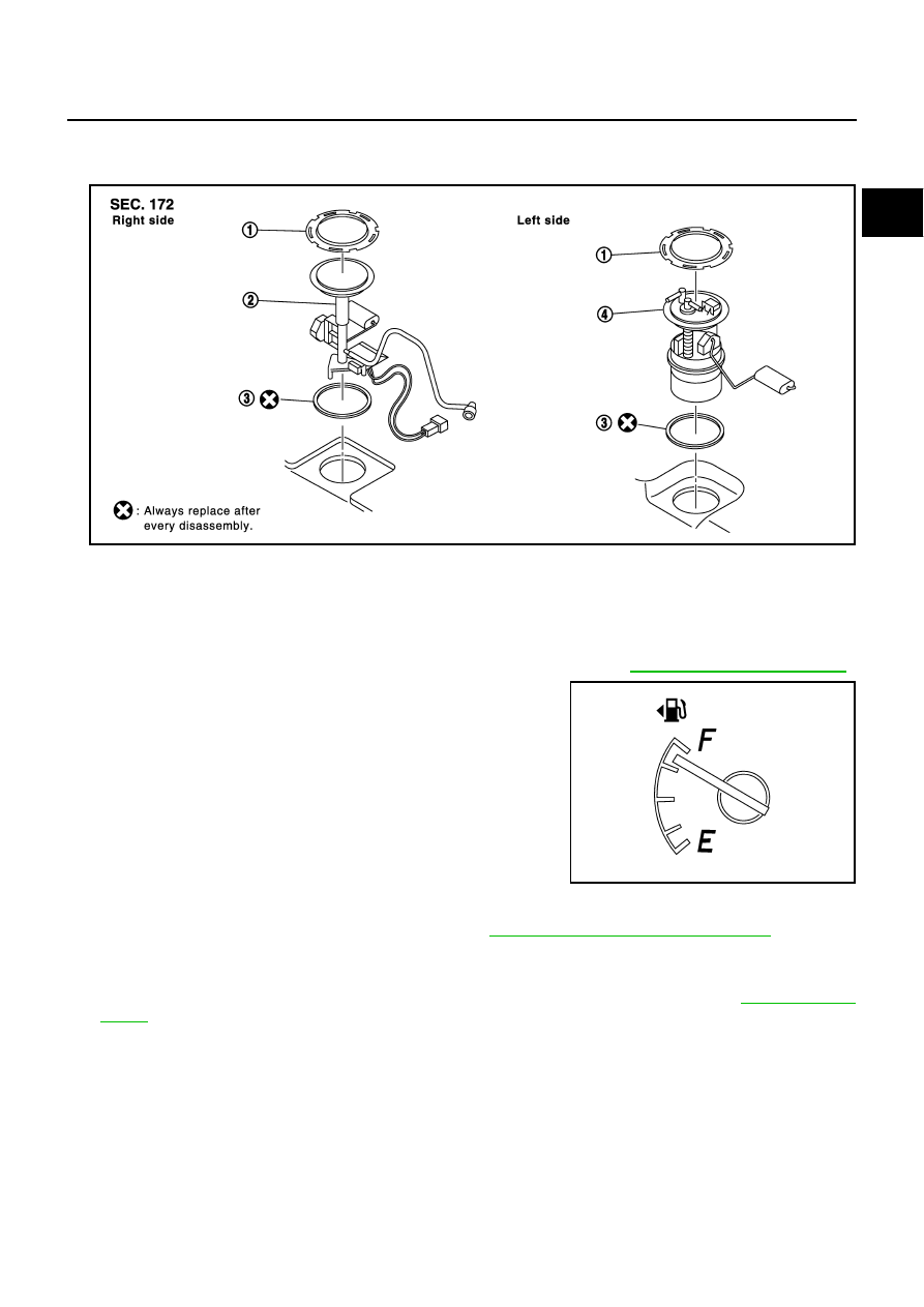
Check fuel level on level place. If gauge indicates more than the
level shown in figure (full or almost full), drain fuel from fuel tank
until gauge indicates level shown in figure or below.

In case fuel pump does not operate, take following procedure.

a.

Insert fuel tube of less than 25 mm (0.98 in) in diameter into fuel
filler tube through fuel filler opening to draw fuel from fuel filler
tube.

b.

Disconnect fuel filler hose from fuel filler tube.

c.

Insert fuel tube into fuel tank through fuel filler hose to draw fuel
from fuel tank.

As a guide, fuel level becomes the position shown in figure or
below when approximately 20 liter (5-1/4 US gal, 4-3/8 Imp gal) of fuel are drained from fuel tank. 

2.

Release the fuel pressure from the fuel lines. Refer to 

EC-66, "FUEL PRESSURE RELEASE"

 .

3.

Open the fuel filler lid.

4.

Open the filler cap and release the pressure inside the fuel tank.

5.

Remove the rear seat cushion trim and pad bolts, then lift up rear seat cushion. Refer to 

SE-129, "REAR

SEAT"

 .

1.

Retainer

2.

Sub fuel level sensor unit

3.

O-ring

4.

Main fuel level sensor unit, fuel filter 
and fuel pump assembly

SBIA0392E

SBIA0393E

FL-6

FUEL LEVEL SENSOR UNIT, FUEL FILTER AND FUEL PUMP ASSEMBLY

Revision; 2004 April

2003 Murano

6.

Remove the inspection hole cover for main and sub fuel level
sensor unit by turning clips counterclockwise by 90

°

.

7.

Disconnect the harness connector and quick connectors for
EVAP/Vent line hose and fuel feed tube

Disconnect EVAP/Vent line hose connector (push in tubs and
pull out).

Disconnect the quick connector for fuel feed tube as follows:

CAUTION:

The quick connector can be disconnected when the tabs
are completely depressed. Do not twist it more than nec-
essary.

Do not use any tools to disconnect the quick connector.

Keep the resin tube away from heat. Be especially careful
when welding near the tube.

Prevent acid liquid such as battery electrolyte etc. from
getting on the resin tube.

Do not bend or twist the resin tube during installation and
disconnection.

Do not remove the remaining retainer on the hard tube (or
the equivalent) except when the resin tube or the retainer
is replaced.

When the resin tube or hard tube (or the equivalent) is
replaced, also replace the retainer with a new one. 

SBIA0394E

SBIA0395E

SFE562A

Retainer color: Green

SBIA0504E

FUEL LEVEL SENSOR UNIT, FUEL FILTER AND FUEL PUMP ASSEMBLY

FL-7

C

D

E

F

G

H

I

J

K

L

M

A

FL

Revision; 2004 April

2003 Murano

To keep clean the connecting portion and to avoid dam-
age and foreign materials, cover them completely with
plastic bags or something similar.

8.

Remove the retainer for main and sub fuel level sensor unit with
fuel tank lock ring wrench (SST) by turning counterclockwise.

9.

Remove main fuel level sensor unit, fuel filter and fuel pump
assembly, and sub fuel level sensor unit.

Raise the main fuel level sensor unit, fuel filter and fuel pump
assembly, and disconnect the fuel hose connector (push in
tabs and pull out) and sub fuel level sensor unit harness con-
nector. 

Raise and release the sub fuel level sensor unit to remove.

INSTALLATION

Install in the reverse order of removal paying attention to the following.

Connect fuel hose connector (push in until it stops) and sub fuel
level sensor unit harness connector.

PBIC0163E

SBIA0411E

SBIA0396E

SBIA0398E

FL-8

FUEL LEVEL SENSOR UNIT, FUEL FILTER AND FUEL PUMP ASSEMBLY

Revision; 2004 April

2003 Murano

Align the direction mark on main and sub fuel level sensor unit
with that on fuel tank as shown in the figure.

Install the inspection hole cover with front mark (arrow) facing
front of the vehicle (Both for RH and LH).
Lock the clips by turning clockwise.

Connect the quick connector as follows.

1.

Check the connection for damage or any foreign materials.

2.

Align the connector with the tube, then insert the connector
straight into the tube until a click is heard.

3.

After connecting, make sure that the connection is secure by fol-
lowing method.

4.

Pull the tube and the connector to make sure they are securely
connected.

Visually confirm that the two retainer tabs are connected to
the connector.

INSPECTION AFTER INSTALLATION

Use the following procedure to check for fuel leaks.

1.

Turn ignition switch “ON” (with engine stopped), then check connections for leaks by applying fuel pres-
sure to fuel piping.

2.

Start the engine and let it idle and make sure there are no fuel leaks at the fuel system connections.

SBIA0397E

SBIA0479E

SFE562A

FUEL TANK

FL-9

C

D

E

F

G

H

I

J

K

L

M

A

FL

Revision; 2004 April

2003 Murano

FUEL TANK

PFP:17202

Removal and Installation

ABS005ZD

REMOVAL

WARNING:

Be sure to read “General Precautions” when working on fuel system. Refer to 

FL-3, "General Precau-

tions"

 .

Drain fuel from the fuel tank if necessary. Refer to step 1 of “REMOVAL” in “FUEL LEVEL SENSOR UNIT,
FUEL FILTER AND FUEL PUMP ASSEMBLY”. Refer to 

FL-5, "REMOVAL"

 .

CAUTION:

For the safety work and to maintain fuel tank gravity at center, drain fuel to the level where fuel
tank weight at left and right becomes equal.

Perform work on level place.

1.

Release fuel pressure from fuel line. Refer to 

EC-66, "FUEL PRESSURE RELEASE"

 .

2.

Open the fuel filler lid.

3.

Open the fuel filler cap and release the pressure inside the fuel tank.

4.

Remove the rear seat cushion trim and pad bolts, then lift up rear seat cushion. Refer to 

SE-129, "REAR

SEAT"

 .

1.

Fuel filler cap

2.

Grommet

3.

Fuel filler tube

4.

Hose clamp

5.

Fuel filler hose

6.

Hose clamp

7.

EVAP/Vent line hose

8.

Hose clamp

9.

EVAP (Recirculation) hose

10. Fuel tank

11. Fuel tank protector

12. Fuel tank mounting band

SBIA0399E

FL-10

FUEL TANK

Revision; 2004 April

2003 Murano

5.

Remove the inspection hole cover for main fuel level sensor
unit, fuel filter and fuel pump assembly (Left side) by turning
clips counterclockwise by 90

°

.

6.

Disconnect harness connector and quick connector for fuel feed
tube.

Disconnect the quick connector, refer to 

FL-5, "FUEL LEVEL

SENSOR UNIT, FUEL FILTER AND FUEL PUMP ASSEM-
BLY"

 .

7.

Remove the center muffler. Refer to 

EX-3, "EXHAUST SYS-

TEM"

 .

8.

Remove the rear propeller shaft (AWD model). Refer to 

PR-4,

"REAR PROPELLER SHAFT"

 .

9.

Remove the parking brake cables. Refer to 

PB-2, "PARKING

BRAKE SYSTEM"

 .

10. Remove the rear final drive assembly (AWD model).

Using a transmission jack, support the bottom of the rear final drive assembly. Refer to 

RFD-10, "REAR

FINAL DRIVE ASSEMBLY"

 .

11. Remove the mounting nuts on the rear suspension member, and lower the transmission jack carefully until

just before the rear suspension member is removed from the stud bolts on the vehicle (AWD model).
Refer to 

RSU-5, "REAR SUSPENSION ASSEMBLY"

 .

12. Remove the fuel tank protector.

13. Disconnect fuel filler hose, EVAP/Vent line hose and EVAP

(Recirculation) hose at the other end than fuel tank side.

SBIA0394E

SBIA0400E

SBIA0401E

FUEL TANK

FL-11

C

D

E

F

G

H

I

J

K

L

M

A

FL

Revision; 2004 April

2003 Murano

14. Remove fuel tank mounting band bolts while supporting fuel

tank.

15. Remove fuel tank.

INSTALLATION

Install in the reverse order of removal paying attention to the following.

Surely clamp fuel hoses and insert hose to the length below.

Be sure hose clamp is not placed on swelled area of fuel tube.

Tighten fuel hose clamp so that the distance between its lugs becomes to the following.

Push the fuel tank mounting band pin to the vehicle side securely.

Before fixing the fuel tank, temporarily install the filler tube.

CAUTION:

Use genuine fuel filler tube mounting bolts or equivalent. Make sure to tighten them to the speci-
fied torque.

To connect the quick connector, refer to 

FL-5, "FUEL LEVEL SENSOR UNIT, FUEL FILTER AND FUEL

PUMP ASSEMBLY"

 .

INSPECTION AFTER INSTALLATION

Make sure there is no fuel leakage at connections in the following steps.

1.

Apply fuel pressure to fuel lines with turning ignition switch “ON” (with engine stopped). Then check for
fuel leaks at connections.

2.

Start the engine and rev it up and check for fuel leaks at connections.

SBIA0402E

Fuel filler hose

: 35 mm (1.38 in)

The other hoses

: 25 mm (0.98 in)

Fuel tank side

: 2 - 6 mm (0.08 - 0.24 in)

Fuel filler tube side

: 5 - 9 mm (0.20 - 0.35 in)

FL-12

SERVICE DATA AND SPECIFICATIONS (SDS)

Revision; 2004 April

2003 Murano

SERVICE DATA AND SPECIFICATIONS (SDS)

PFP:00030

Standard and Limit

ABS00349

Tightening Torque

ABS0034A

Unit: N·m (kg-m, ft-lb)

Unit: N·m (kg-m, in-lb)*

Fuel tank capacity

Approx. 82   (21-5/8 US gal, 18 Imp gal)

Fuel tank mounting band

37.0 - 49.0 (3.8 - 4.9, 28 - 36) 

Fuel filler tube 

7.8 - 10.4 (0.8 - 1.0, 69 - 92)*

Fuel tank protector

4.3 - 5.8 (0.43 - 0.59, 38 - 51)*

FSU-1

FRONT SUSPENSION

E  SUSPENSION

CONTENTS

C

D

F

G

H

I

J

K

L

M

SECTION 

FSU

A

B

FSU

Revision; 2004 April

2003 Murano

FRONT SUSPENSION

PRECAUTIONS .......................................................... 2

Caution ..................................................................... 2

PREPARATION ........................................................... 3

Special Service Tools  ............................................... 3
Commercial Service Tools ........................................ 3

NOISE, VIBRATION AND HARSHNESS (NVH) 
TROUBLESHOOTING ................................................ 4

NVH Troubleshooting Chart  ..................................... 4

FRONT SUSPENSION ASSEMBLY ........................... 5

On-Vehicle Inspection and Service  .......................... 5

INSPECTION OF TRANSVERSE LINK END 
PLAY ..................................................................... 5
STRUT INSPECTION  ........................................... 5

Wheel Alignment Inspection ..................................... 5

DESCRIPTION ...................................................... 5
PRELIMINARY CHECK  ........................................ 5
INSPECTION OF CAMBER, CASTER AND 
KINGPIN INCLINATION ANGLES.  ....................... 5

Components ............................................................. 7
Removal and Installation  .......................................... 8

COIL SPRING AND STRUT  ....................................... 9

Removal and Installation  .......................................... 9

REMOVAL ............................................................. 9

INSTALLATION ..................................................... 9

Disassembly and Assembly ...................................... 9

DISASSEMBLY ..................................................... 9
INSPECTION AFTER DISASSEMBLY ................ 10
ASSEMBLY ......................................................... 10

TRANSVERSE LINK ................................................. 12

Removal and Installation  ........................................ 12

REMOVAL ........................................................... 12
INSPECTION AFTER REMOVAL  ....................... 12
INSTALLATION ................................................... 12

STABILIZER BAR  ..................................................... 14

Removal and Installation  ........................................ 14

REMOVAL ........................................................... 14
INSPECTION AFTER REMOVAL  ....................... 14
INSTALLATION ................................................... 14

FRONT SUSPENSION MEMBER ............................. 15

Removal and Installation  ........................................ 15

REMOVAL ........................................................... 15
INSPECTION AFTER REMOVAL  ....................... 15
INSTALLATION ................................................... 15

SERVICE DATA AND SPECIFICATIONS (SDS)  ...... 16

Wheel Alignment (Unladen) .................................... 16
Ball Joint  ................................................................. 16
Wheelarch Height (Unladen*) ................................. 16

FSU-2

PRECAUTIONS

Revision; 2004 April

2003 Murano

PRECAUTIONS

PFP:00001

Caution

AES000G7

When installing rubber bushings, final tightening must be carried out under unladen conditions with tires
on ground. Oil will shorten the life of rubber bushings. Be sure to wipe off any spilled oil.

Unladen conditions mean that fuel, engine coolant and lubricant are full. Spare tire, jack, hand tools and
mats are in designated positions.

After servicing suspension parts, be sure to check wheel alignment.

Caulking nuts are not reusable. Always use new ones when installing. Since new caulking nuts are pre-
oiled, tighten as they are. 

PREPARATION

FSU-3

C

D

F

G

H

I

J

K

L

M

A

B

FSU

Revision; 2004 April

2003 Murano

PREPARATION

PFP:00002

Special Service Tools

AES000G8

The actual shapes of Kent-Moore tools may differ from those of special service tools illustrated here.

Commercial Service Tools

AES000G9

Tool number
 (Kent-Moore No.)
Tool name

Description

KV991040S0
(        —       )
CCK gauge attachment
1. Plate
2. Guide bolts
3. Nuts
4. Springs
5. Center plate
6. KV99104020 Adapter A
  a: 72 mm (2.83 in) dia.
7. KV99104030 Adapter B
  b: 65 mm (2.56 in) dia.
8. KV99104040 Adapter C
  c: 57 mm (2.24 in) dia.
9. KV99104050 Adapter D
  d: 53.4 mm (2.102 in) dia.

Measuring wheel alignment

ST35652000
(        —       )
Strut attachment

Disassembling and assembling strut

ST3127S000
(See J25742-1)
Preload gauge
1. GC91030000
              Torque wrench (J25765)
2. HT62940000 (   —   )
               Socket adapter (1/2

)

3. HT62900000 (   —   )
               Socket adapter (3/8

)

Measuring sliding torque of ball joint

S-NT498

ZZA0807D

NT124

Tool name

Description

Spring compressor

Removing coil spring

Power tool

Removing wheel nuts

Removing undercover

Removing front suspension compo-
nents parts

S-NT717

PBIC0190E

FSU-4

NOISE, VIBRATION AND HARSHNESS (NVH) TROUBLESHOOTING

Revision; 2004 April

2003 Murano

NOISE, VIBRATION AND HARSHNESS (NVH) TROUBLESHOOTING

PFP:00003

NVH Troubleshooting Chart

AES000GA

Use chart below to help you find the cause of the symptom. If necessary, repair or replace these parts.

×

: Applicable

Reference page

FSU-

7

FSU-

10

FSU-

10

FSU-

5

FSU-

14

NVH 

in

 PR s

e

c

tio

n

NVH 

in

 RFD s

e

c

tio

n

N

V

H

 i

n

 R

AX and R

S

U

 sect

io

n

NVH in

 W

T

 s

e

c

ti

o

n

NVH in

 W

T

 s

e

c

ti

o

n

NVH 

in

 RAX s

e

c

tio

n

NVH 

in

 BR s

e

c

tio

n

NVH 

in

 PS s

e

c

tio

n

Possible cause and SUSPECTED PARTS

Im

pr

o

per

 i

n

st

al

la

ti

on

lo

osen

ess

S

tr

u

t d

e

fo

rm

at

ion,

 d

a

m

age 

or

 d

e

fl

ec

ti

on

Bus

h

ing or

 m

oun

ti

ng det

er

io

ra

ti

on

P

a

rt

s

 in

te

rf

e

re

n

c

e

Spr

ing f

a

ti

gue

Sus

pens

io

n l

o

o

s

ene

ss

In

co

rr

ect

 w

h

e

e

l a

lignm

en

t

S

ta

b

ili

z

er

 bar

 f

a

ti

g

u

e

PROPELL

E

R SHAF

T

DIFFERENTIAL

REAR AXLE AND R

E

AR 

SUSPENSION

TIRES

ROAD W

H

EEL

D

R

IV

E

 SH

AF

T

BRAKES

STEERING

Symptom

FRONT SUSPENSION

Noise

× ×

×

×

×

×

×

× ×

×

×

× ×

×

Shake

× ×

×

×

×

×

×

×

×

× ×

×

Vibration

× ×

×

×

×

×

×

×

×

×

Shimmy

× ×

×

×

×

×

×

×

×

×

Judder

× ×

×

×

×

×

×

×

Poor quality ride or han-
dling

× ×

×

×

×

× ×

×

×

×

FRONT SUSPENSION ASSEMBLY

FSU-5

C

D

F

G

H

I

J

K

L

M

A

B

FSU

Revision; 2004 April

2003 Murano

FRONT SUSPENSION ASSEMBLY

PFP:54010

On-Vehicle Inspection and Service

AES000GB

Make sure the mounting conditions (looseness, back lash) of each component and component statues (wear,
damage) are normal.

INSPECTION OF TRANSVERSE LINK END PLAY

1.

Set front wheels in a straight-ahead position. Do not depress brake pedal.

2.

Measure axial end play of transverse link ball joint by prying between suspension arm and front axle with
a iron bar or something similar.

CAUTION:

Be careful not to damage ball joint boot.

STRUT INSPECTION

Check strut for oil leakage, damage and replace if necessary.

Wheel Alignment Inspection

AES000GC

DESCRIPTION

Measure wheel alignment under unladen conditions. “Unladen conditions” means that fuel, engine cool-
ant, and lubricant are full. Spare tire, jack, hand tools and mats are in designated positions.

PRELIMINARY CHECK

1.

Check tires for improper air pressure and wear.

2.

Check road wheels for runout.

3.

Check wheel bearing axial end play.

4.

Check transverse link ball joint axial end play.

5.

Check strut operation.

6.

Check each mounting point of axle and suspension for looseness and deformation.

7.

Check each link, rod, and member for cracks, deformation and other damage.

8.

Check vehicle posture.

INSPECTION OF CAMBER, CASTER AND KINGPIN INCLINATION ANGLES.

Camber, caster, kingpin inclination angles cannot be adjusted.

Before inspection, mount front wheels onto turning radius gauge. Mount rear wheels onto a stand that has
same height so vehicle will remain horizontal.

Using a CCK Gauge

1.

Remove wheel nuts (3), and install a guide bolt (SST) to hub
bolt.

2.

Screw adapter (SST) into plate body (SST) until it contacts body
tightly.

3.

Screw center plate (SST) into plate body (SST).

4.

Insert plate (SST) on guide bolt (SST). Put spring in, and then
evenly screw in guide bolt nut (SST). When fastening guide bolt
nut, do not completely compress spring.

Axial end play

: 0 mm (0 in)

SEIA0240E

FSU-6

FRONT SUSPENSION ASSEMBLY

Revision; 2004 April

2003 Murano

5.

Place the dent of alignment gauge onto the projection of center
plate (SST) and tightly contact them to measure.

CAUTION:

If camber, caster, or kingpin inclination angle is outside
the standard, check front suspension parts for wear and
damage, and replace suspect parts if necessary.

Kingpin inclination angle is reference value, no inspec-
tion is required. (Due to the type of suspension, the king-
pin inclination angle cannot be measured correctly using a normal alignment tester.)

Toe-In Inspection

Measure toe-in using the following procedure.

WARNING:

Always perform the following procedure on a flat surface.

Make sure that no person is in front of vehicle before push-
ing it.

1.

Bounce front of vehicle up and down to stabilize the posture.

2.

Push vehicle straight ahead about 5 m (16 ft).

3.

Put a mark on base line of the tread (rear side) of both tires at
the same height of hub center. These are measuring points.

4.

Measure distance “A” (rear side).

5.

Push vehicle slowly ahead to rotate wheels 180 degrees (1/2
turn).

If wheels have rotated more than 180 degrees (1/2 turn), try the
above procedure again from the beginning. Never push vehicle
backward.
6.

Measure distance “B” (front side).

Camber, caster, kingpin inclination angles:

Refer to 

FSU-16, "SERVICE DATA AND SPECIFI-

CATIONS (SDS)"

 .

SEIA0241E

AFA050

Total toe-in

: Refer to 

FSU-16, "SERVICE DATA 

AND SPECIFICATIONS (SDS)"

 .

SFA234AC

FRONT SUSPENSION ASSEMBLY

FSU-7

C

D

F

G

H

I

J

K

L

M

A

B

FSU

Revision; 2004 April

2003 Murano

Components

AES000GD

SEIA0312E

FSU-8

FRONT SUSPENSION ASSEMBLY

Revision; 2004 April

2003 Murano

Removal and Installation

AES000GE

Remove suspension assembly with engine assembly from vehicle. Refer to “ENGINE MECHANICAL” section

EM-95, "ENGINE ASSEMBLY"

 .

1.

Upper mounting plate

2.

Mounting insulator

3.

Mounting insulator bracket

4.

Mounting bearing

5.

Spring upper seat

6.

Spring upper rubber seat

7.

Coil spring

8.

Spring lower rubber seat

9.

Bound bumper

10. Strut

11. Stabilizer clamp

12. Stabilizer bushing

13. Stabilizer

14. Connecting rod

15. Strut assembly

16. Front axle

17. Member stay

18. Transverse link

19. Front suspension member

20. Rebound stopper

21. Damper assembly

22. Air guide


Content      ..     133      134      135      136     ..