Nissan Murano Z50 (2003 year). Manual - part 95
DTC P0133, P0153 HO2S1
EC-239
C
D
E
F
G
H
I
J
K
L
M
A
EC
Revision; 2004 April
2003 Murano
Specification data are reference values and are measured between each terminal and ground.
CAUTION:
Do not use ECM ground terminals when measuring input/output voltage. Doing so may result in dam-
age to the ECM's transistor. Use a ground other than ECM terminals, such as the ground.
Diagnostic Procedure
ABS004E1
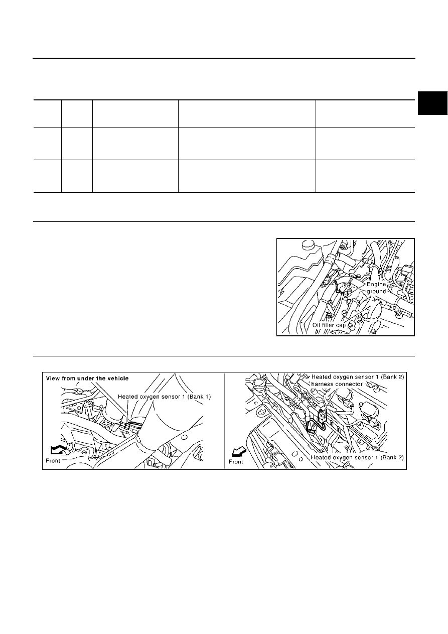
1.
RETIGHTEN GROUND SCREWS
1.
Turn ignition switch “OFF”.
2.
Loosen and retighten engine ground screws.
>> GO TO 2.
2.
RETIGHTEN HEATED OXYGEN SENSOR 1
Loosen and retighten heated oxygen sensor 1.
>> GO TO 3.
TER-
MINAL
NO.
WIRE
COLOR
ITEM
CONDITION
DATA (DC Voltage)
16
LG
Heated oxygen sensor 1
(bank 2)
[Engine is running]
●
Warm-up condition
●
Engine speed is 2,000 rpm.
0 - Approximately 1.0V
(Periodically change)
78
B
Sensors' ground
(Heated oxygen sensor)
[Engine is running]
●
Warm-up condition
●
Idle speed
Approximately 0V
PBIB1298E
Tightening torque: 40 - 50 N·m (4.1 - 5.1 kg-m, 30 - 37 ft-lb)
PBIB1301E