Nissan Murano Z50 (2003 year). Manual - part 33
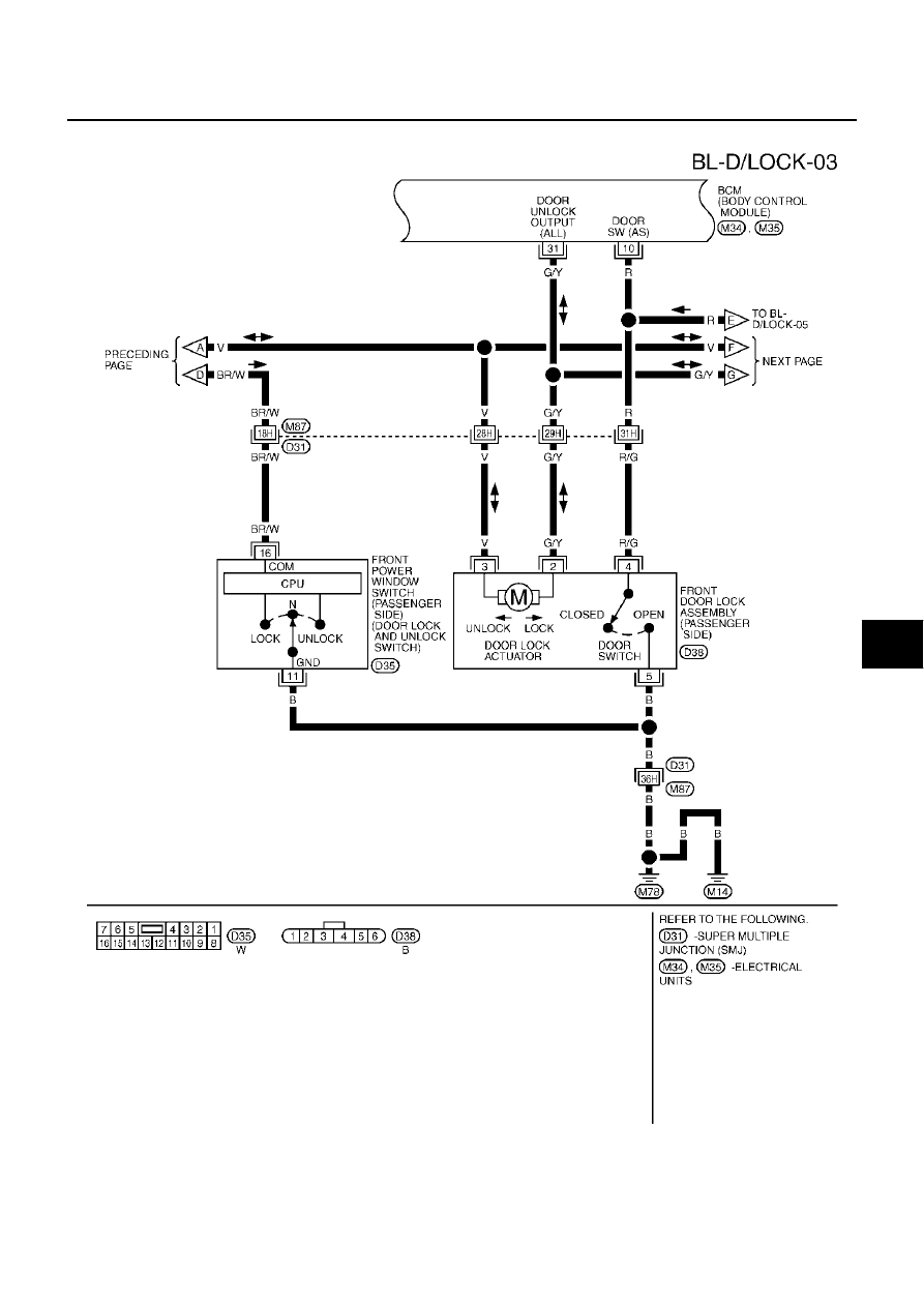
POWER DOOR LOCK SYSTEM
BL-51
C
D
E
F
G
H
J
K
L
M
A
B
BL
Revision; 2004 April
2003 Murano
FIG. 3
TIWA0360E
|
|
|
POWER DOOR LOCK SYSTEM BL-51 C D E F G H J K L M A B BL Revision; 2004 April 2003 Murano FIG. 3 TIWA0360E |