Nissan Murano Z50 (2003 year). Manual - part 31


  Index      Manuals     Nissan Murano Z50 (2003 year) - Service and Repair Manual


Search            copyright infringement  


Content      ..     29      30      31      32     ..


Nissan Murano Z50 (2003 year). Manual - part 31


RADIATOR CORE SUPPORT

BL-19

C

D

E

F

G

H

J

K

L

M

A

B

BL

Revision; 2004 April

2003 Murano

RADIATOR CORE SUPPORT

PFP:62500

Removal and Installation

AIS005GI

REMOVAL

1.

Remove radiator cover grill. Refer to 

EM-14, "AIR CLEANER AND AIR DUCT"

2.

Remove air duct. Refer to 

EM-14, "AIR CLEANER AND AIR DUCT"

3.

Remove front bumper, bumper reinforcement and bumper stay. Refer to 

EI-14, "Removal and Installation"

.

4.

Remove hood lock assembly, remove hood lock cable. Refer to 

BL-15, "Removal and Installation of Hood

Assembly"

 .

5.

Remove headlamp (LH/RH). Refer to 

LT-55, "Removal and Installation"

  or 

LT-101, "Removal and Installa-

tion"

 .

6.

Remove crash zone sensor. Refer to 

SRS-46, "Removal and Installation"

 .

7.

Remove the hood switch Refer to 

BL-142, "Component Parts and Harness Connector Location"

 .

8.

Remove the undercover.

9.

Remove the ambient sensor. Refer to 

ATC-128, "Removal and Installation"

 .

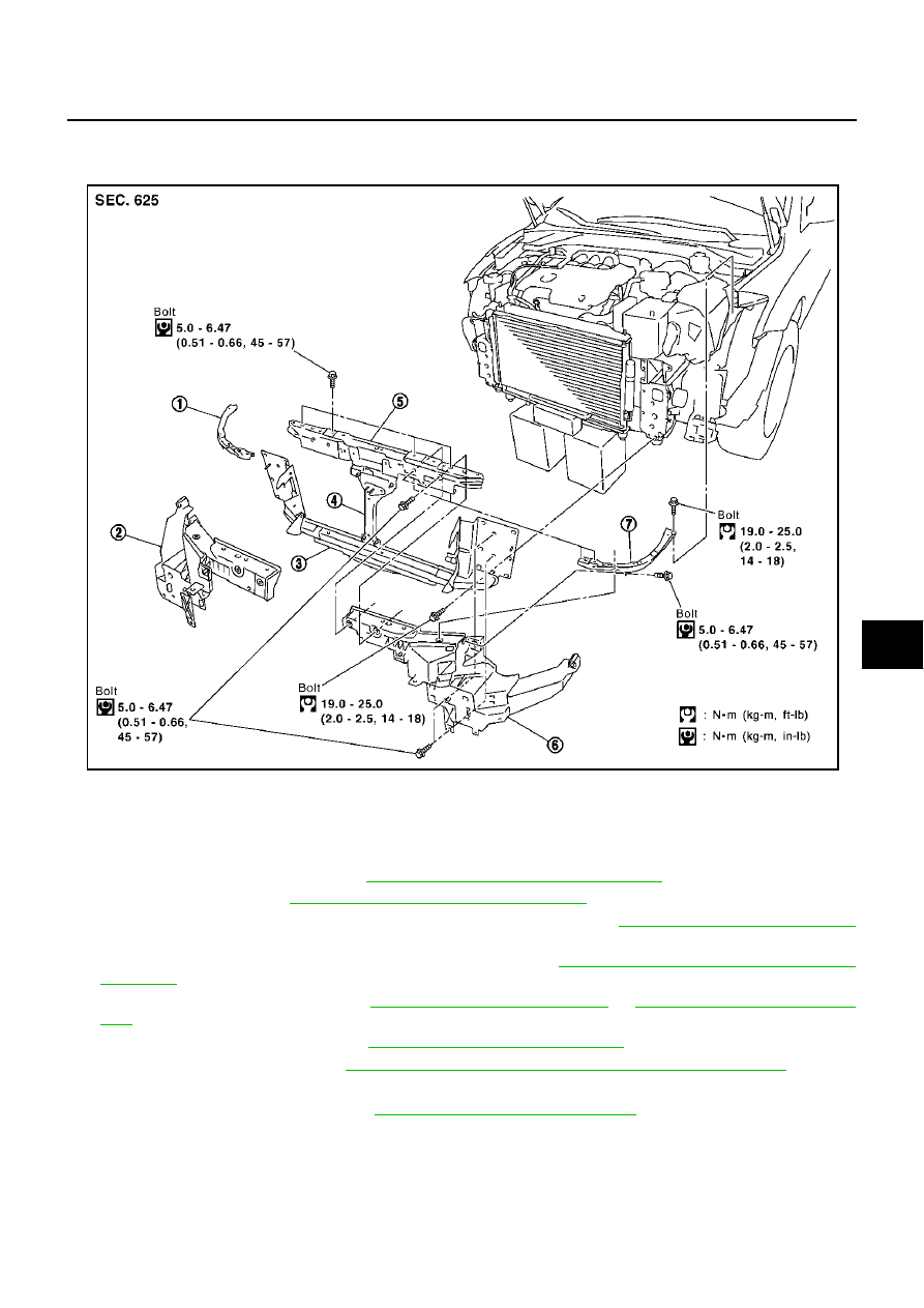
1. Radiator core support upper side (RH)

2.

Radiator core support side (RH)

3. Radiator core support lower

4. Radiator core support center

5.

Radiator core support upper center

6. Radiator core support side (LH)

7. Radiator core support upper side (LH)

PIIA4405E

BL-20

RADIATOR CORE SUPPORT

Revision; 2004 April

2003 Murano

10. Remove mounting bolt washer tank.

11. Remove mounting harness clip on radiator core support assembly, the harness is separate.

12. Remove the radiator core support upper side.

CAUTION:

Put a wooden block under the radiator assembly to prevent
the radiator assembly from falling.

13. Remove the radiator core support center.

14. Remove the radiator core support upper center.
15. Remove the radiator core support side.

PIIA4406E

PIIA4407E

PIIA4411E

PIIA4408E

RADIATOR CORE SUPPORT

BL-21

C

D

E

F

G

H

J

K

L

M

A

B

BL

Revision; 2004 April

2003 Murano

16. Remove radiator core support assembly.

17. After removing radiator core support assembly, the following

parts are separate.

Radiator core support lower

INSTALLATION

Install in the reverse order of removal.

PIIA4410E

BL-22

FRONT FENDER

Revision; 2004 April

2003 Murano

FRONT FENDER

PFP:63100

Removal and Installation

AIS003C3

REMOVAL

1.

Remove the front bumper. Refer to 

EI-14, "Removal and Installation"

 .

2.

Remove the headlamp. Refer to 

LT-55, "Removal and Installation"

  or 

LT-101, "Removal and Installation"

 .

3.

Remove the front fender protector. Refer to 

EI-22, "Removal and Installation"

 .

4.

Remove the mounting bolt and remove the front fender.

CAUTION:

While removing use a shop cloth to protect body from damaging.

INSTALLATION

Install in the reverse order of removal.

CAUTION:

After installing, apply touch-up paint (the body color) onto the head of the front fender mounting
bolts.

After installing, check front fender adjustment. Refer to 

BL-125, "Fitting Adjustment"

  and 

BL-13,

"Fitting Adjustment"

 .

1.

Front fender

PIIA6077E

POWER DOOR LOCK SYSTEM

BL-23

C

D

E

F

G

H

J

K

L

M

A

B

BL

Revision; 2004 April

2003 Murano

POWER DOOR LOCK SYSTEM

PFP:24814

Component Parts and Harness Connector Location

AIS002EW

PIIB1502E

BL-24

POWER DOOR LOCK SYSTEM

Revision; 2004 April

2003 Murano

System Description

AIS002EX

Power is supplied at all times

to BCM terminal 7

through 50A fusible link (letter F , located in the fuse and fusible link box).

to key switch terminal 3

through 10A fuse [No. 21, located in the fuse block (J/B)].

When key switch is ON (key is inserted in ignition key cylinder), power is supplied

to BCM terminal 62

through key switch terminal 4.

When front door switch (driver side) is ON (door is OPEN), ground is supplied

to BCM terminal 14 and unified meter and A/C amp. terminal 8

through front door switch (driver side) terminals 4 and 5

through grounds M14 and M78.

When front door switch (passenger side) is ON (door is OPEN), ground is supplied

to BCM terminal 10 and unified meter and A/C amp. terminal 7

through front door switch (passenger side) terminals 4 and 5

through grounds M14 and M78.

When rear door switch LH is ON (door is OPEN), ground is supplied

to unified meter and A/C amp. terminal 18

through rear door switch LH terminals 4 and 5

through grounds B7 and B20.

When rear door switch RH is ON (door is OPEN), ground is supplied

to unified meter and A/C amp. terminal 17

through rear door switch RH terminals 4 and 5

through grounds B105 and B116.

Combination meter send door open signal to BCM with CAN communication system.
When back door switch is ON (back door is OPEN), ground is supplied

to BCM terminal 18

through back door switch terminals 1 and 3

through grounds B7 and B20.

When door is locked and unlocked with power window main switch (door lock and unlock switch), ground is
supplied

to CPU of power window main switch

through power window main switch (door lock and unlock switch) terminal 17

through grounds M14 and M78.

Then power window main switch (door lock and unlock switch) operation signal is supplied.

to BCM terminal 74

through power window main switch (door lock and unlock switch) terminal 14.

When door is locked and unlocked with front power window switch (passenger side) (door lock and unlock
switch), ground is supplied

to CPU of front power window switch (passenger side)

through front power window switch (passenger side) (door lock and unlock switch) terminal 11

through grounds M14 and M78.

Then front power window switch (passenger side) (door lock and unlock switch) operation signal is supplied

to BCM terminal 74

through front power window switch (passenger side) (door lock and unlock switch) terminal 16.

When door is locked with door key cylinder switch, ground is supplied

to power window main switch (door lock and unlock switch) terminal 4

through door key cylinder switch terminals 1 and 5

POWER DOOR LOCK SYSTEM

BL-25

C

D

E

F

G

H

J

K

L

M

A

B

BL

Revision; 2004 April

2003 Murano

through grounds M14 and M78.

Then door key cylinder switch operation signal (lock) is supplied

to BCM terminal 74

through power window main switch (door lock and unlock switch) terminal 14.

When the door is unlocked with door key cylinder switch, ground is supplied

to power window main switch (door lock and unlock switch) terminal 6 

through front door key cylinder switch (driver side) terminal 6 and 5

through grounds M14 and M78.

Then door key cylinder switch operation signal (unlock) is supplied

to BCM terminal 74

through power window main switch (door lock and unlock switch) terminal 14.

BCM is connected to power window main switch and front power window switch (passenger side) as serial
link.

POWER WINDOW SERIAL LINK

Power window main switch, front power window switch (passenger side) and BCM transmit and receive the
signal by power window serial link.
The under mentioned signal is transmitted from power window main switch to BCM.

Door lock and unlock switch signal.

The under mentioned signal is transmitted from front power window switch (passenger side) to BCM.

Door lock and unlock switch signal.

OUTLINE
Functions Available by Operating the Door Lock and Unlock Switches on Driver's Door and 
Passenger's Door

Interlocked with the locking operation of door lock and unlock switch, door lock actuators of all doors and
fuel lid lock actuator are locked.

Interlocked with the unlocking operation of door lock and unlock switch, door lock actuators of all doors
and fuel lid lock actuator are unlocked.

Functions Available by Operating the Door key Cylinder Switch

Interlocked with the locking operation of door key cylinder, door lock actuators of all doors and fuel lid lock
actuator are locked.

When door key cylinder is unlocked, door lock actuator driver side is unlocked.

When door key cylinder is unlocked for the second time within 5 seconds after the first operation, door
lock actuators on all doors and fuel lid lock actuator are unlocked.

Unlock mode can be changed using “DOOR LOCK-UNLOCK SET” mode in “WORK SUPPORT”.
Refer to 

BL-58, "WORK SUPPORT"

 .

Key Reminder Door System

When door lock and unlock switch is operated to lock doors with ignition key put in ignition key cylinder and
any door (include back door) open, all door lock actuators are locked and then unlocked.
Key reminder mode can be changed using “ANTI-LOCK OUT SET” mode in “WORK SUPPORT”.
Refer to 

BL-58, "WORK SUPPORT"

 .

BL-26

POWER DOOR LOCK SYSTEM

Revision; 2004 April

2003 Murano

CAN Communication System Description

AIS003CL

CAN (Controller Area Network) is a serial communication line for real time application. It is an on-vehicle mul-
tiplex communication line with high data communication speed and excellent error detection ability. Many elec-
tronic control units are equipped onto a vehicle, and each control unit shares information and links with other
control units during operation (not independent). In CAN communication, control units are connected with 2
communication lines (CAN H line, CAN L line) allowing a high rate of information transmission with less wiring.
Each control unit transmits/receives data but selectively reads required data only.

CAN Communication Unit For 2WD Models

AIS003KH

×

: Applicable

Body type

Wagon

Axle

2WD

Engine

VQ35DE

Transmission

CVT

Brake control

ABS

VDC

Low tire pressure warning 
system

×

×

×

×

×

×

×

×

Navigation system

×

×

×

×

×

×

×

×

Automatic drive positioner

×

×

×

×

×

×

×

×

CAN communication unit

ECM

×

×

×

×

×

×

×

×

×

×

×

×

×

×

×

×

TCM

×

×

×

×

×

×

×

×

×

×

×

×

×

×

×

×

Low tire pressure warning 
control unit

×

×

×

×

×

×

×

×

Display unit

×

×

×

×

×

×

×

×

Display control unit

×

×

×

×

×

×

×

×

Data link connector

×

×

×

×

×

×

×

×

×

×

×

×

×

×

×

×

BCM

×

×

×

×

×

×

×

×

×

×

×

×

×

×

×

×

Unified meter and A/C amp.

×

×

×

×

×

×

×

×

×

×

×

×

×

×

×

×

Steering angle sensor

×

×

×

×

×

×

×

×

Driver seat control unit

×

×

×

×

×

×

×

×

ABS actuator and electric 
unit (control unit)

×

×

×

×

×

×

×

×

×

×

×

×

×

×

×

×

IPDM E/R

×

×

×

×

×

×

×

×

×

×

×

×

×

×

×

×

CAN communication type

BL-27, "TYPE 1/TYPE 2/TYPE 3/TYPE 4/TYPE 5/

TYPE 6/TYPE 7/TYPE 8"

BL-32, "TYPE 9/TYPE10/TYPE 11/TYPE 12/

TYPE 13/TYPE 14/TYPE 15/TYPE 16"

POWER DOOR LOCK SYSTEM

BL-27

C

D

E

F

G

H

J

K

L

M

A

B

BL

Revision; 2004 April

2003 Murano

TYPE 1/TYPE 2/TYPE 3/TYPE 4/TYPE 5/TYPE 6/TYPE 7/TYPE 8
System Diagram

Type1

Type2

Type3

SKIA4902E

SKIA4903E

SKIA4904E

BL-28

POWER DOOR LOCK SYSTEM

Revision; 2004 April

2003 Murano

Type4

Type5

Type6

SKIA4905E

SKIA4906E

SKIA4907E

POWER DOOR LOCK SYSTEM

BL-29

C

D

E

F

G

H

J

K

L

M

A

B

BL

Revision; 2004 April

2003 Murano

Type7

Type8

SKIA4908E

SKIA4909E

BL-30

POWER DOOR LOCK SYSTEM

Revision; 2004 April

2003 Murano

Input/output Signal Chart

T: Transmit   R: Receive

Signals

ECM

TCM

Low 

tire 

pres-

sure 

warn-

ing 

control 

unit

Dis-
play 

unit

Dis-
play 

control 

unit

BCM

Uni-

fied 

meter 

and A/

C amp.

Driver 

seat 

control 

unit

ABS 

actua-

tor and 

elec-

tric unit 

(con-

trol 

unit)

IPDM 

E/R

Engine speed signal

T

R

R

R

R

Engine status signal

T

R

Engine coolant temperature signal

T

R

CVT position indicator signal

T

R

Second position signal 

R

T

Second position indicator signal

T

R

Engine and CVT integrated control 
signal

T

R

R

T

Accelerator pedal position signal 

T

Closed throttle position signal

T

Wide open throttle position signal

T

Key switch signal

T

R

Ignition switch signal

T

R

R

P range signal

T

R

Stop lamp switch signal

R

T

Fuel consumption monitor signal

T

R

CVT self-diagnosis signal

R

T

ABS operation signal

R

T

Air conditioner switch signal

R

T

A/C compressor request signal

T

R

A/C compressor feedback signal

T

R

Blower fan motor switch signal

R

T

A/C control signal

T

T

R

R

R

T

Cooling fan speed request signal

T

R

Position lights request signal

T

R

R

Low beam request signal

T

R

Low beam status signal

R

T

High beam request signal

T

R

R

High beam status signal

R

T

Front fog lights request signal

T

R

Vehicle speed signal

R

R

T

R

R

R

R

T

R

Sleep request 1 signal

T

R

Sleep request 2 signal

T

R

Door switch signal

R

T

R

R

T

R

R

R

Turn indicator signal

T

R

POWER DOOR LOCK SYSTEM

BL-31

C

D

E

F

G

H

J

K

L

M

A

B

BL

Revision; 2004 April

2003 Murano

Key fob ID signal

T

R

Key fob door unlock signal

T

R

Seat belt buckle switch signal

R

T

Oil pressure switch signal

R

T

T

R

Buzzer output signal

T

R

Fuel level sensor signal

R

T

Fuel level low warning signal

R

R

T

Malfunction indicator lamp signal

T

R

ASCD SET lamp signal

T

R

ASCD CRUISE lamp signal

T

R

Input shaft revolution signal

R

T

Output shaft revolution signal

R

T

Front wiper request signal

T

R

Front wiper stop position signal

R

T

Rear window defogger switch signal

T

R

Rear window defogger control signal

R

R

R

T

Hood switch signal

R

T

Theft warning horn request signal

T

R

Horn chirp signal

T

R

Tire pressure signal

T

R

Tire pressure data signal

T

R

R

ABS warning lamp signal

R

T

Brake warning lamp signal

R

T

System setting signal

T

T

R

Parking brake switch signal

R

T

Signals

ECM

TCM

Low 

tire 

pres-

sure 

warn-

ing 

control 

unit

Dis-
play 

unit

Dis-
play 

control 

unit

BCM

Uni-

fied 

meter 

and A/

C amp.

Driver 

seat 

control 

unit

ABS 

actua-

tor and 

elec-

tric unit 

(con-

trol 

unit)

IPDM 

E/R

BL-32

POWER DOOR LOCK SYSTEM

Revision; 2004 April

2003 Murano

TYPE 9/TYPE10/TYPE 11/TYPE 12/TYPE 13/TYPE 14/TYPE 15/TYPE 16
System Diagram

Type9

Type10

Type11

SKIA4910E

SKIA4911E

SKIA4912E

POWER DOOR LOCK SYSTEM

BL-33

C

D

E

F

G

H

J

K

L

M

A

B

BL

Revision; 2004 April

2003 Murano

Type12

Type13

Type14

SKIA4913E

SKIA4914E

SKIA4915E

BL-34

POWER DOOR LOCK SYSTEM

Revision; 2004 April

2003 Murano

Type15

Type16

SKIA4916E

SKIA4917E


Content      ..     29      30      31      32     ..