Nissan Murano Z51 (2008 year). Manual - part 126
DLK-548
< ON-VEHICLE REPAIR >
[WITHOUT INTELLIGENT KEY SYSTEM]
FRONT DOOR
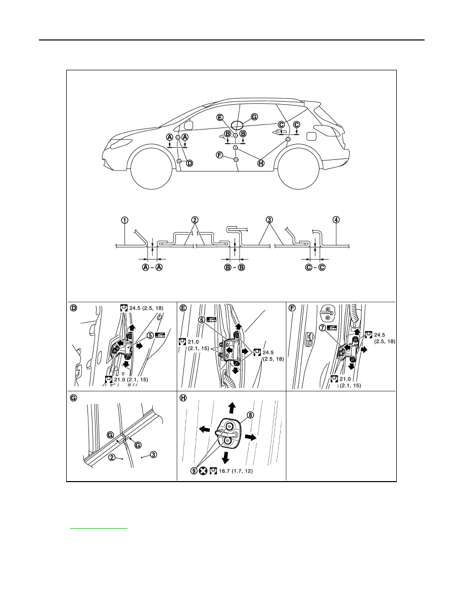
DOOR ASSEMBLY : Adjustment
INFOID:0000000004749800
Check the clearance and surface height between front door and each part by visually and touching.
If the clearance and the surface height are out of specification, adjust them according to the procedures
shown below.
1.
Front fender
2.
Front door
3.
Rear door
4.
Body side outer
5.
Front door hinge
6.
Rear door hinge (upper)
7.
Rear door hinge (lower)
8.
Door striker
9.
TORX bolt
Refer to
for symbols in the figure.
JMKIA3687GB
Revision: 2008 October
2009 Murano