Nissan Murano Z51 (2008 year). Manual - part 74
BRC-24
< FUNCTION DIAGNOSIS >
[VDC/TCS/ABS]
ABS
Component Description
INFOID:0000000003305338
1.
Steering angle sensor
2.
ABS warning lamp
3.
Brake warning lamp
4.
VDC OFF indicator lamp
5.
SLIP indicator lamp
6.
ABS actuator and electric unit (con-
trol unit)
7.
Front wheel sensor
8.
Yaw rate/side/decel G sensor
9.
VDC OFF switch
10. Rear wheel sensor
A.
Back of spiral cable assembly
B.
Combination meter
C.
Engine room (right side)
D.
Steering knuckle
E.
Under center console
F.
Instrument driver lower panel
G.
Rear axle
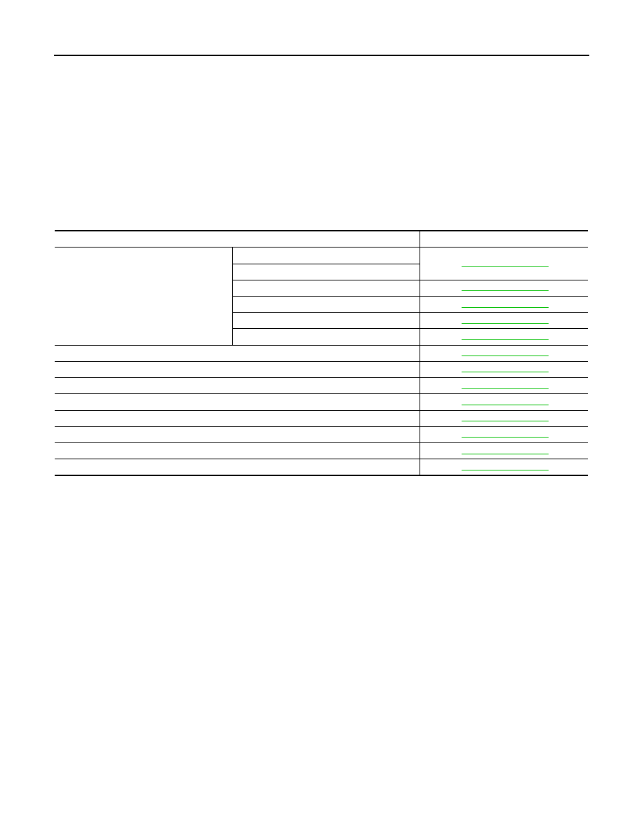
Component parts
Reference
ABS actuator and electric unit (control unit)
Pump
Motor
Actuator relay (Main relay)
Solenoid valve
VDC switch-over valve (CV1, CV2)
VDC switch-over valve (SV1, SV2)
Wheel sensor
Yaw rate/side/decel G sensor
Steering angle sensor
VDC OFF switch
ABS warning lamp
Brake warning lamp
VDC OFF indicator lamp
SLIP indicator lamp
Revision: 2008 October
2009 Murano