Nissan Murano Z51 (2008 year). Manual - part 75
BRC-40
< COMPONENT DIAGNOSIS >
[VDC/TCS/ABS]
C1105, C1106, C1107, C1108 WHEEL SENSOR
Is the inspection result normal?
YES
>> GO TO 6.
NO
>> Repair or replace damaged parts.
6.
CHECK DATA MONITOR
1.
Turn the ignition switch OFF.
2.
Connect each wheel sensor connector.
3.
Check wheel sensor signal. Refer to
BRC-40, "Component Inspection"
Is the inspection result normal?
YES
>> Replace ABS actuator and electric unit (control unit).
NO
>> Repair or replace damaged parts.
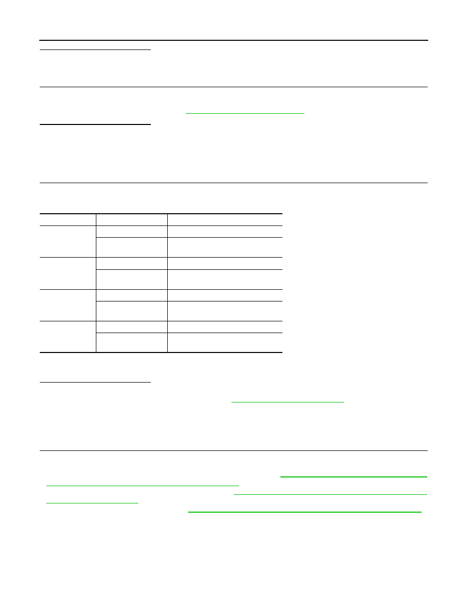
Component Inspection
INFOID:0000000003390266
1.
CHECK DATA MONITOR
On “DATA MONITOR”, select “FR LH SENSOR”, “FR RH SENSOR”, “RR LH SENSOR”, and “RR RH SEN-
SOR”, and check the vehicle speed.
NOTE:
Confirm tire pressure is normal.
Is the inspection result normal?
YES
>> INSPECTION END
NO
>> Proceed to diagnosis procedure. Refer to
.
Special Repair Requirement
INFOID:0000000003390263
1.
ADJUSTMENT OF STEERING ANGLE SENSOR NEUTRAL POSITION, CALIBRATION OF YAW RATE/
SIDE/DECEL G SENSOR AND CALIBRATION OF PRESSURE SENSOR
After removing/replacing an ABS actuator and electric unit (control unit), be sure to perform the following pro-
cedure.
• Adjustment of steering angle sensor neutral position: Refer to
BRC-9, "ADJUSTMENT OF STEERING
ANGLE SENSOR NEUTRAL POSITION : Description"
.
• Calibration of yaw rate/side/decel G sensor: Refer to
BRC-10, "CALIBRATION OF YAW RATE/SIDE/DECEL
.
• Calibration of pressure sensor: Refer to
BRC-11, "CALIBRATION OF PRESSURE SENSOR : Description"
>> END
Wheel sensor
Condition
Vehicle speed (DATA MONITOR)
FR LH SENSOR
Vehicle stopped
0 [km/h (MPH)]
Vehicle running (Note)
Nearly matches the speedometer dis-
play (
±
10% or less)
FR RH SENSOR
Vehicle stopped
0 [km/h (MPH)]
Vehicle running (Note)
Nearly matches the speedometer dis-
play (
±
10% or less)
RR LH SENSOR
Vehicle stopped
0 [km/h (MPH)]
Vehicle running (Note)
Nearly matches the speedometer dis-
play (
±
10% or less)
RR RH SENSOR
Vehicle stopped
0 [km/h (MPH)]
Vehicle running (Note)
Nearly matches the speedometer dis-
play (
±
10% or less)
Revision: 2008 October
2009 Murano