Nissan Murano. Manual - part 878


  Главная      Nissan     Nissan Murano (2014 year) - Service Manual


поиск по сайту            


содержание   ..  876  877  878  879   ..


Nissan Murano. Manual - part 878


INL-24

< DTC/CIRCUIT DIAGNOSIS >

INTERIOR ROOM LAMP CONTROL CIRCUIT

Does continuity exist?

YES

>> Replace the map lamp or the personal lamp.

NO

>> Repair the harnesses or connectors.

3.

CHECK INTERIOR ROOM LAMP CONTROL SHORT CIRCUIT

1.

Turn ignition switch OFF.

2.

Disconnect BCM connector, map lamp connector and personal lamp connector.

3.

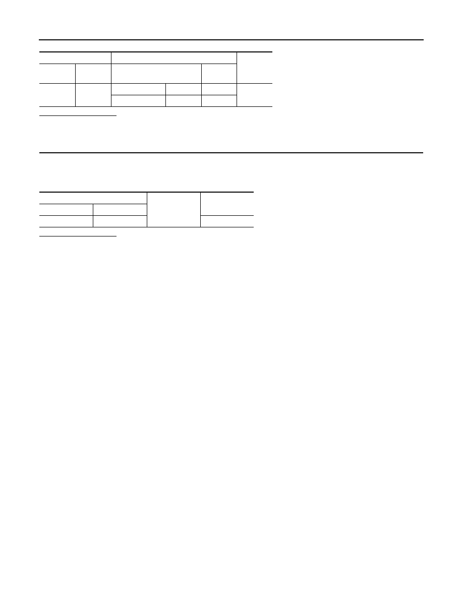
Check continuity between BCM harness connector and ground.

Does continuity exist?

YES

>> Repair the harnesses or connectors.

NO

>> Replace BCM.

BCM

Map lamp/personal lamp

Continuity

Connec-

tor

Terminal

Connector

Terminal

M119

19

Map lamp

R19

2

Existed

Personal lamp

R21

3

BCM

Ground

Continuity

Connector

Terminal

M119

19

Not existed

STEP LAMP CIRCUIT

INL-25

< DTC/CIRCUIT DIAGNOSIS >

C

D

E

F

G

H

I

J

K

M

A

B

INL

N

O

P

STEP LAMP CIRCUIT

Description

INFOID:0000000009718421

Controls the step lamp (ground side) to turn the step lamp ON and OFF.

Component Function Check

INFOID:0000000009718422

CAUTION:

 Before performing the diagnosis, check that the following is normal.
• Interior room lamp power supply
• Step lamp bulb

1.

CHECK STEP LAMP OPERATION

CONSULT ACTIVE TEST

1.

Turn the ignition switch ON.

2.

Select "STEP LAMP TEST" of BCM (INT LAMP) active test item.

3.

With operating the test items, check that step lamp turns ON/OFF.

Does the step lamp turn ON/OFF?

YES

>> Step lamp circuit is normal.

NO

>> Refer to 

INL-25, "Diagnosis Procedure"

.

Diagnosis Procedure

INFOID:0000000009718423

1.

CHECK STEP LAMP OUTPUT

CONSULT ACTIVE TEST

1.

Turn the ignition switch OFF.

2.

Remove the step lamp bulbs (driver side and passenger side).

3.

Turn the ignition switch ON.

4.

Select “STEP LAMP TEST” of BCM (INT LAMP) active test item.

5.

 With operating the test item, check continuity between BCM harness connector and the ground.

Is the measurement value normal?

YES

>> GO TO 2.

Fixed ON>>GO TO 3.
Fixed OFF>>Replace BCM.

2.

CHECK STEP LAMP OPEN CIRCUIT

1.

Turn the ignition switch OFF.

2.

Disconnect BCM connector, and step lamp connector.

3.

Check continuity between BCM harness connector and step lamp harness connector.

On

: Step lamp ON

Off

: Step lamp OFF

BCM

Ground

Test item

Continuity

Connector

Terminal

STEP LAMP 

TEST

M119

7

On

Existed

Off

Not existed

BCM

Step lamp

Continuity

Connector

Terminal

Connector

Terminal

M119

7

Driver 
side

D17

2

Existed

Passen-
ger side

D51

2

INL-26

< DTC/CIRCUIT DIAGNOSIS >

STEP LAMP CIRCUIT

Does continuity exist?

YES

>> Replace step lamp.

NO

>> Repair harnesses or connectors.

3.

CHECK STEP LAMP SHORT CIRCUIT

1.

Turn the ignition switch OFF.

2.

Check continuity between BCM harness connector and the ground.

Does continuity exist?

YES

>> Repair the harnesses or connectors.

NO

>> Replace BCM.

BCM

Ground

Continuity

Connector

Terminal

M119

7

Not existed

PUSH-BUTTON IGNITION SWITCH ILLUMINATION CIRCUIT

INL-27

< DTC/CIRCUIT DIAGNOSIS >

C

D

E

F

G

H

I

J

K

M

A

B

INL

N

O

P

PUSH-BUTTON IGNITION SWITCH ILLUMINATION CIRCUIT

Description

INFOID:0000000009718424

Provides the power supply and the ground to control the push-button ignition switch illumination.

Component Function Check

INFOID:0000000009718425

1.

CHECK PUSH-BUTTON IGNITION SWITCH ILLUMINATION OPERATION

CONSULT ACTIVE TEST

1.

Turn the ignition switch ON.

2.

Select “ENGINE SW ILLUMI” of BCM (INTELLIGENT KEY) active test item.

3.

With operating the test items, check that the push-button ignition switch illumination turns ON/OFF

Does the push-button ignition switch illumination turn ON/OFF?

YES

>> Push-button ignition switch illumination circuit is normal.

NO

>> Refer to 

INL-27, "Diagnosis Procedure"

.

Diagnosis Procedure

INFOID:0000000009718426

1.

CHECK ILLUMINATION CONTROL SWITCHING OPERATION

1.

Turn the ignition switch ON.

2.

With operating the lighting switch, check that the push-button ignition switch illumination turns ON/OFF

Does the push-button ignition switch illumination turn ON/OFF?

YES

>> GO TO 2.

NO

>> GO TO 3.

2.

CHECK PUSH-BUTTON IGNITION SWITCH ILLUMINATION GROUND CIRCUIT

1.

Turn the ignition switch OFF.

2.

Disconnect BCM connector and the push-button ignition switch connector.

3.

Check continuity between BCM harness connector and the push-button ignition switch harness connector.

Does the continuity exist?

YES

>> Replace BCM.

NO

>> Repair the harness or the connector.

3.

CHECK PUSH-BUTTON IGNITION SWITCH ILLUMINATION POWER SUPPLY OUTPUT

CONSULT ACTIVE TEST

1.

Turn the ignition switch ON.

2.

Select “ENGINE SW ILLUMI” of BCM (INTELLIGENT KEY) active test item.

3.

With operating the test item, check voltage between BCM harness connector and the ground.

On

: Push-button ignition switch illumination ON

Off

: Push-button ignition switch illumination OFF

Condition

Push-button ignition switch illumina-

tion

• Ignition switch ON
• Lighting switch 1ST

ON

• Ignition switch OFF
• Lighting switch OFF
• Driver door LOCK

OFF

BCM

Push-button ignition switch

Continuity

Connector

Terminal

Connector

Terminal

M119

14

M101

2

Existed


содержание   ..  876  877  878  879   ..