Nissan Murano. Manual - part 824


  Главная      Nissan     Nissan Murano (2014 year) - Service Manual


поиск по сайту            


содержание   ..  822  823  824  825   ..


Nissan Murano. Manual - part 824


HAC-70

< DTC/CIRCUIT DIAGNOSIS >

[WITHOUT 7 INCH DISPLAY]

BLOWER MOTOR

BLOWER MOTOR

Description

INFOID:0000000009722088

COMPONENT DESCRIPTION
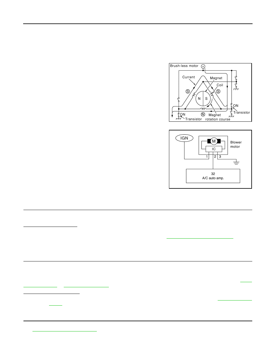
Brush-less Motor

The blower motor utilizes a brush-less motor with a rotating magnet.
Quietness is improved over previous motors where the brush was
the point of contact and the coil rotated.

Blower Motor Circuit

Component Function Check

INFOID:0000000009722089

1.

CHECK OPERATION

1.

Warm up the engine.

2.

Operate the fan control dial. Check that the fan speed and indicator are switched for all fan speeds. 

Does it operate normally?

YES

>> INSPECTION END

NO

>> Perform trouble diagnosis for the blower motor. Refer to 

HAC-70, "Diagnosis Procedure"

.

Diagnosis Procedure

INFOID:0000000009722090

1.

CHECK WITH SELF-DIAGNOSIS FUNCTION OF CONSULT

1.

Using CONSULT, perform “SELF-DIAGNOSIS RESULTS” of HVAC. 

2.

Check if any DTC No. is displayed in the self-diagnosis results. 

NOTE:
If DTC is displayed along with DTC U1000 or U1010, first diagnose the DTC U1000 or U1010. Refer to 

HAC-

44, "DTC Logic"

 or 

HAC-45, "DTC Logic"

Is any DTC No. displayed?

YES

>> Perform the diagnosis that is applicable to the sensor and actuator. Refer to 

HAC-106, "DTC

Index"

NO

>> GO TO 2.

2.

CHECK WITH ACTIVE TEST OF CONSULT

1.

Using CONSULT, perform “HVAC TEST” “ACTIVE TEST” of HVAC to check each output device. Refer to

HAC-40, "CONSULT Function"

.

NOTE:
Perform the ACTIVE TEST after starting the engine because the compressor is operated. 

ZHA152H

JSIIA0999ZZ

BLOWER MOTOR

HAC-71

< DTC/CIRCUIT DIAGNOSIS >

[WITHOUT 7 INCH DISPLAY]

C

D

E

F

G

H

J

K

L

M

A

B

HAC

N

O

P

2.

Check that the blower motor control signal changes according to each indicator signal. 

NOTE:

Perform the inspection of each output device after starting the engine because the compressor is operated. 

Does it operate normally?

YES

>> INSPECTION END

NO

>> GO TO 3.

3.

CHECK POWER SUPPLY FOR BLOWER MOTOR

1.

Disconnect blower motor connector.

2.

Turn ignition switch ON.

3.

Check voltage between blower motor harness connector and ground.

Is the inspection result normal?

YES

>> GO TO 4.

NO

>> GO TO 7.

4.

CHECK BLOWER MOTOR GROUND CIRCUIT

1.

Turn ignition switch OFF.

2.

Check continuity between blower motor harness connector and ground.

Is the inspection result normal?

YES

>> GO TO 5.

NO

>> Repair harness or connector.

5.

CHECK BLOWER MOTOR CIRCUIT CONTINUITY

1.

Disconnect A/C auto amp. connector.

2.

Check continuity between blower motor harness connector and A/C auto amp. harness connector.

Is the inspection result normal?

YES

>> GO TO 6.

Test item

MODE 1

MODE 2

MODE 3

MODE 4

MODE 5

MODE 6

MODE 7

Mode door position

VENT1

VENT2

B/L1

B/L2

FOOT

D/F

DEF

Intake door position

REC

REC

20%FRE

20%FRE

FRE

FRE

FRE

Air mix door position 
(driver & passenger 
side)

FULL COLD

FULL HOT

FULL COLD

FULL HOT

FULL HOT

FULL HOT

FULL HOT

Blower motor duty ratio

35%

35%

61%

61%

81%

81%

35%

Compressor (Magnet 
clutch)

ON

ON

ON

ON

OFF

OFF

ON

Upper ventilator door

OPEN

SHUT

OPEN

SHUT

SHUT

SHUT

SHUT

(+)

(

)

Voltage

Blower motor

Connector

Terminal

M98

1

Ground

Battery voltage

Blower motor

Continuity

Connector

Terminal

M98

3

Ground

Existed

Blower motor

A/C auto amp.

Continuity

Connector

Terminal

Connector

Terminal

M98

2

M50

32

Existed

HAC-72

< DTC/CIRCUIT DIAGNOSIS >

[WITHOUT 7 INCH DISPLAY]

BLOWER MOTOR

NO

>> Repair harness or connector.

6.

CHECK A/C AUTO AMP. OUTPUT SIGNAL

1.

Reconnect blower motor connector and A/C auto amp. connector.

2.

Turn ignition switch ON.

3.

Set MODE switch to the VENT position.

4.

Check the output waveform between blower motor harness connector and ground using an oscilloscope,
while varying the fan speed from 1 to 7. 

Is the inspection result normal?

YES

>> Replace the blower motor. 

NO

>> Replace the A/C auto amp. 

7.

CHECK POWER VOLTAGE OF BLOWER RELAY

1.

Turn the ignition switch OFF.

2.

Remove the blower relay. Refer to 

PG-91, "Fuse, Connector and Terminal Arrangement"

3.

Turn the ignition switch ON.

4.

Check the voltage between blower relay fuse block side terminal and ground. Refer to 

PG-91, "Fuse, Con-

nector and Terminal Arrangement"

 for relay terminal assignment. 

Is the inspection result normal?

YES

>> GO TO 8.

NO

>> Inspection the power supply circuit. Refer to 

PG-47, "Wiring Diagram - IGNITION POWER SUP-

PLY -"

.

8.

CHECK BLOWER RELAY

1.

Turn the ignition switch OFF.

2.

Install the blower relay. Refer to 

PG-91, "Fuse, Connector and Terminal Arrangement"

3.

Turn the ignition switch ON.

4.

Check the operating sound of blower relay. 

Is the inspection result normal?

YES

>> GO TO 9.

NO

>> Replace the blower relay. 

9.

CHECK FUSE

Check 15A fuses (Nos. 21 and 22). 
NOTE:

JPIIA0616GB

(+)

(

)

Voltage

Blower relay

1

Ground

Battery voltage

3

BLOWER MOTOR

HAC-73

< DTC/CIRCUIT DIAGNOSIS >

[WITHOUT 7 INCH DISPLAY]

C

D

E

F

G

H

J

K

L

M

A

B

HAC

N

O

P

Refer to 

PG-91, "Fuse, Connector and Terminal Arrangement"

 for fuse location. 

Is the inspection result normal?

YES

>> Repair the harnesses or connectors.

NO

>> Replace the fuse after repairing the applicable circuit.

Component Inspection

INFOID:0000000009722091

1.

CHECK BLOWER MOTOR

1.

Remove the blower motor. Refer to 

VTL-33, "Exploded View"

2.

Check that the blower motor rotates smoothly. 

Is the inspection result normal?

YES

>> INSPECTION END

NO

>> Replace blower motor.


содержание   ..  822  823  824  825   ..