содержание .. 728 729 730 731 ..
Nissan Murano. Manual - part 730
EXL-332
< ECU DIAGNOSIS INFORMATION >
[HALOGEN TYPE]
IPDM E/R (INTELLIGENT POWER DISTRIBUTION MODULE ENGINE ROOM)
IPDM E/R (INTELLIGENT POWER DISTRIBUTION MODULE ENGINE
ROOM)
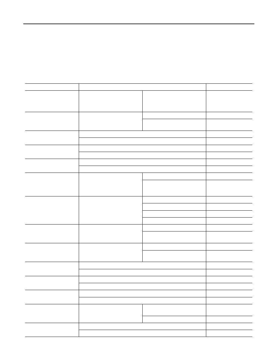
Reference Value
INFOID:0000000010092659
VALUES ON THE DIAGNOSIS TOOL
NOTE:
The following table includes information (items) inapplicable to this vehicle. For information (items) applicable
to this vehicle, refer to CONSULT display items.
Monitor Item
Condition
Value/Status
MOTOR FAN REQ
Engine idle speed
Changes depending on engine
coolant temperature, air conditioner
operation status, vehicle speed,
etc.
1/2/3/4
AC COMP REQ
Engine running
A/C switch OFF
Off
A/C switch ON
(Compressor is operating)
On
TAIL&CLR REQ
Lighting switch OFF
Off
Lighting switch 1ST, 2ND, HI or AUTO (Light is illuminated)
On
HL LO REQ
Lighting switch OFF
Off
Lighting switch 2ND HI or AUTO (Light is illuminated)
On
HL HI REQ
Lighting switch OFF
Off
Lighting switch HI
On
FR FOG REQ
Lighting switch 2ND or
AUTO (Light is illuminated)
Front fog lamp switch OFF
Off
• Front fog lamp switch ON
• Daytime running light activated
(Only for Canada)
On
FR WIP REQ
Ignition switch ON
Front wiper switch OFF
Stop
Front wiper switch INT
1LOW
Front wiper switch LO
Low
Front wiper switch HI
Hi
WIP AUTO STOP
Ignition switch ON
Front wiper stop position
STOP P
Any position other than front wiper
stop position
ACT P
WIP PROT
Ignition switch ON
Front wiper operates normally
Off
Front wiper stops at fail-safe opera-
tion
BLOCK
IGN RLY1 -REQ
Ignition switch OFF or ACC
Off
Ignition switch ON
On
IGN RLY
Ignition switch OFF or ACC
Off
Ignition switch ON
On
PUSH SW
Release the push-button ignition switch
Off
Press the push-button ignition switch
On
INTER/NP SW
Ignition switch ON
Selector lever in any position other
than P or N
Off
Selector lever in P or N position
On
ST RLY CONT
Ignition switch ON
Off
At engine cranking
On