содержание .. 653 654 655 656 ..
Nissan Murano. Manual - part 655
EXL-32
< SYSTEM DESCRIPTION >
[XENON TYPE]
DIAGNOSIS SYSTEM (IPDM E/R)
ACTIVE TEST
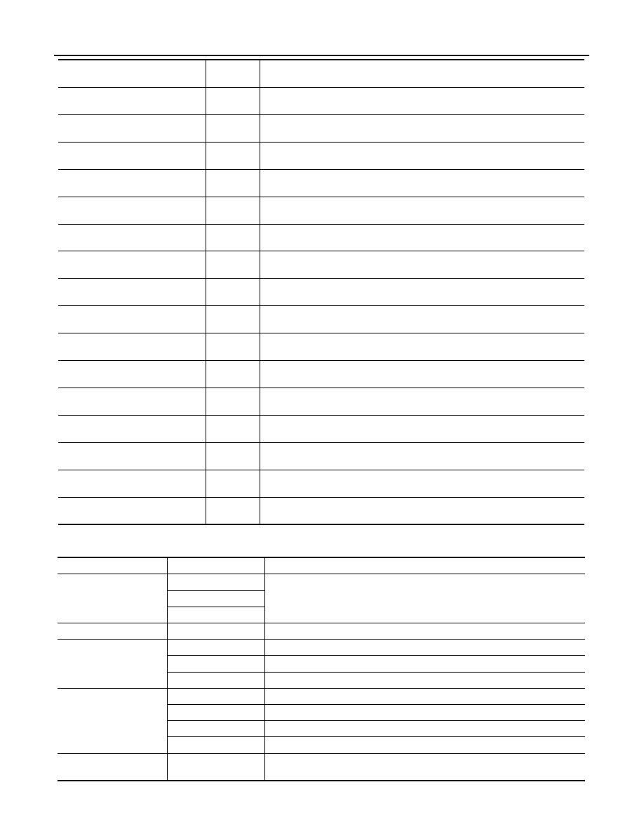
IGN RLY
[Off/On]
×
Displays the status of the ignition relay judged by IPDM E/R.
PUSH SW
[Off/On]
Displays the status of the push-button ignition switch judged by IPDM E/R.
INTER/NP SW
[Off/On]
Displays the status of the shift position judged by IPDM E/R.
ST RLY CONT
[Off/On]
Displays the status of the starter relay status signal received from BCM via CAN
communication.
IHBT RLY -REQ
[Off/On]
Displays the status of the starter control relay signal received from BCM via CAN
communication.
ST/INHI RLY
[Off/ ST ON/INHI ON/UNKWN]
Displays the status of the starter relay and starter control relay judged by IPDM
E/R.
DETENT SW
[Off/On]
Displays the status of the CVT shift selector (detention switch) judged by IPDM E/
R.
S/L RLY -REQ
[Off/On]
NOTE:
The item is indicated, but not monitored.
S/L STATE
[LOCK/UNLOCK/UNKWN]
NOTE:
The item is indicated, but not monitored.
DTRL REQ
[Off/On]
NOTE:
The item is indicated, but not monitored.
OIL P SW
[Open/Close]
Displays the status of the oil pressure switch judged by IPDM E/R.
HOOD SW
[Off/On]
NOTE:
The item is indicated, but not monitored.
HL WASHER REQ
[Off/On]
NOTE:
The item is indicated, but not monitored.
THFT HRN REQ
[Off/On]
Displays the status of the theft warning horn request signal received from BCM
via CAN communication.
HORN CHIRP
[Off/On]
Displays the status of the horn reminder signal received from BCM via CAN com-
munication.
CRNRNG LMP REQ
[Off/On]
NOTE:
The item is indicated, but not monitored.
Monitor Item
[Unit]
MAIN SIG-
NALS
Description
Test item
Operation
Description
CORNERING LAMP
Off
NOTE:
The item is indicated, but cannot be tested.
LH
RH
HORN
On
Operates horn relay for 20 ms.
FRONT WIPER
Off
OFF
Lo
Operates the front wiper relay.
Hi
Operates the front wiper relay and front wiper high relay.
MOTOR FAN
1
OFF
2
Operates the cooling fan relay-1.
3
Operates the cooling fan relay-2.
4
Operates the cooling fan relay-2 and cooling fan relay-3.
HEAD LAMP WASHER
On
NOTE:
The item is indicated, but cannot be tested.