содержание .. 652 653 654 655 ..
Nissan Murano. Manual - part 654
EXL-28
< SYSTEM DESCRIPTION >
[XENON TYPE]
DIAGNOSIS SYSTEM (BCM)
*: Factory setting
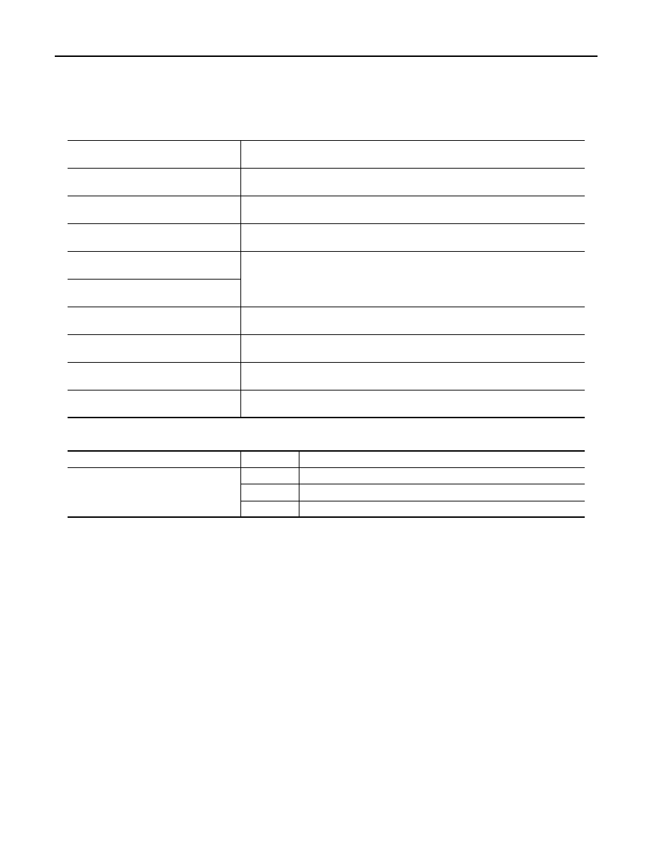
DATA MONITOR
NOTE:
The following table includes information (items) inapplicable to this vehicle. For information (items) applicable
to this vehicle, refer to CONSULT display items.
ACTIVE TEST
Monitor item
[Unit]
Description
REQ SW-DR
[On/Off]
The switch status input from the request switch (driver side)
REQ SW-AS
[On/Off]
The switch status input from the request switch (passenger side)
PUSH SW
[On/Off]
The switch status input from the push-button ignition switch
TURN SIGNAL R
[On/Off]
Each switch status that BCM detects from the combination switch reading function
TURN SIGNAL L
[On/Off]
HAZARD SW
[On/Off]
The switch status input from the hazard switch
RKE-LOCK
[On/Off]
Lock signal status received from the remote keyless entry receiver
RKE-UNLOCK
[On/Off]
Unlock signal status received from the remote keyless entry receiver
RKE-PANIC
[On/Off]
Panic alarm signal status received from the remote keyless entry receiver
Test item
Operation
Description
FLASHER
RH
Outputs the voltage to blink the right side turn signal lamps.
LH
Outputs the voltage to blink the left side turn signal lamps.
Off
Stops the voltage to turn the turn signal lamps OFF.