содержание .. 649 650 651 652 ..
Nissan Murano. Manual - part 651
EXL-16
< SYSTEM DESCRIPTION >
[XENON TYPE]
FRONT FOG LAMP SYSTEM
FRONT FOG LAMP SYSTEM
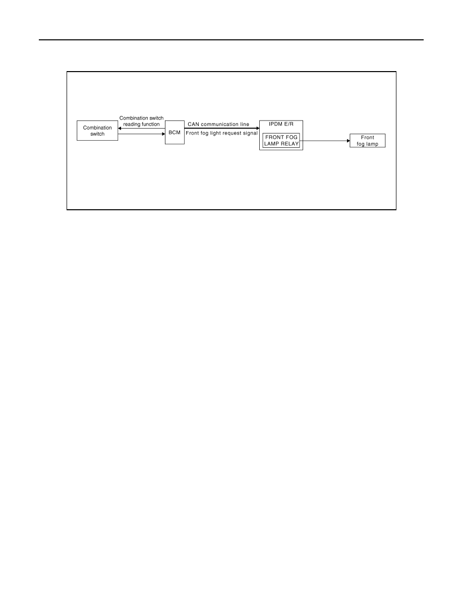
System Diagram
INFOID:0000000009722876
System Description
INFOID:0000000009722877
OUTLINE
Front fog lamp is controlled by combination switch reading function and front fog lamp control function of BCM,
and relay control function of IPDM E/R.
FRONT FOG LAMP OPERATION
• BCM detects the combination switch condition by the combination switch reading function.
• BCM transmits the front fog light request signal to IPDM E/R with CAN communication according to the front
fog lamp ON condition.
Front fog lamp ON condition
- Front fog lamp switch ON with headlamp ON (except for the high beam ON)
• IPDM E/R turns the integrated front fog lamp relay ON, and turns the front fog lamp ON according to the
front fog light request signal.
JPLIA0004GB