содержание .. 648 649 650 651 ..
Nissan Murano. Manual - part 650
EXL-12
< SYSTEM DESCRIPTION >
[XENON TYPE]
DAYTIME RUNNING LIGHT SYSTEM
DAYTIME RUNNING LIGHT SYSTEM
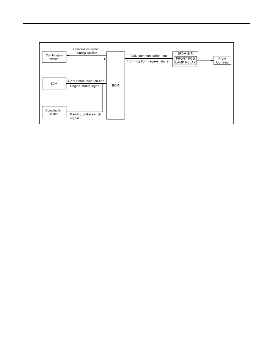
System Diagram
INFOID:0000000009722868
System Description
INFOID:0000000009722869
OUTLINE
• Turns the front fog lamp ON as the daytime running light.
• Daytime running light is controlled by daytime running light control function and combination switch reading
function of BCM, and relay control function of IPDM E/R.
DAYTIME RUNNING LIGHT OPERATION
• BCM detects the combination switch condition by the combination switch reading function.
• BCM detects the vehicle condition depending on the following signals.
- Engine condition signal (received from ECM with CAN communication)
- Parking brake switch signal (received from combination meter with CAN communication)
• BCM transmits the front fog light request signal to IPDM E/R with CAN communication according to the day-
time running light ON condition.
Daytime running light ON condition
- While the engine running with the parking brake released
Daytime running light OFF condition
- Engine stopped
- Headlamp ON (Passing included)
• IPDM E/R turns the integrated front fog lamp relay ON and turns the front fog lamp ON according to the front
fog light request signal.
JPLIA0803GB