Nissan Murano. Manual - part 646


  Главная      Nissan     Nissan Murano (2014 year) - Service Manual


поиск по сайту            


содержание   ..  644  645  646  647   ..


Nissan Murano. Manual - part 646


EX-2

< PRECAUTION >

PRECAUTIONS

PRECAUTION

PRECAUTIONS

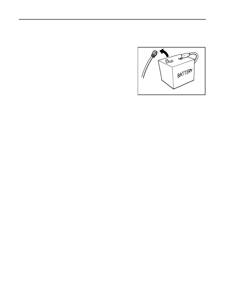
Precautions for Removing of Battery Terminal

INFOID:0000000009953392

•  When removing the 12V battery terminal, turn OFF the ignition

switch and wait at least 30 seconds.
NOTE:
ECU may be active for several tens of seconds after the ignition
switch is turned OFF. If the battery terminal is removed before ECU
stops, then a DTC detection error or ECU data corruption may
occur.

•  For vehicles with the 2-batteries, be sure to connect the main bat-

tery and the sub battery before turning ON the ignition switch.
NOTE:
If the ignition switch is turned ON with any one of the terminals of
main battery and sub battery disconnected, then DTC may be
detected.

•  After installing the 12V battery, always check "Self Diagnosis Result" of all ECUs and erase DTC.

NOTE:
The removal of 12V battery may cause a DTC detection error.

Removal and Installation

INFOID:0000000009718025

CAUTION:

• Be sure to use genuine exhaust system parts or equivalents which are specially designed for heat

resistance, corrosion resistance, and shape.

• Perform the operation with the exhaust system fully cooled down because the system will be hot

just after engine stops. 

• Be careful not to cut your hand on the heat insulator edge.

SEF289H

PREPARATION

EX-3

< PREPARATION >

C

D

E

F

G

H

I

J

K

L

M

A

EX

N

P

O

PREPARATION

PREPARATION

Commercial Service Tool

INFOID:0000000009718026

Tool name

Description

Power tool

Loosening nuts and bolts

PBIC0190E

EX-4

< PERIODIC MAINTENANCE >

EXHAUST SYSTEM

PERIODIC MAINTENANCE

EXHAUST SYSTEM

Inspection

INFOID:0000000009718027

Check exhaust pipes, muffler, and mounting for improper attach-
ment, leakage, cracks, damage or deterioration.
• If anything is found, repair or replace damaged parts.

SMA211A

EXHAUST SYSTEM

EX-5

< REMOVAL AND INSTALLATION >

C

D

E

F

G

H

I

J

K

L

M

A

EX

N

P

O

REMOVAL AND INSTALLATION

EXHAUST SYSTEM

Exploded View

INFOID:0000000009718028

Removal and Installation

INFOID:0000000009718029

REMOVAL

Disconnect each joint and mounting using power tool.

INSTALLATION

Note the following, and install in the reverse order of removal.
• If exhaust front tube stud bolts were removed, and install them and tighten to the specified torque below.

CAUTION:

• Always replace exhaust tube gaskets with new ones when reassembling.
• If heat insulator is badly deformed, repair or replace it. If deposits such as mud pile up on the heat

insulator, remove them.

1.

Main muffler

2.

Mounting rubber

3.

Gasket

4.

Mounting rubber

5.

Center muffler

6.

Mounting rubber

7.

Gasket

8.

Mounting rubber

9.

Exhaust front tube

10. Gasket

: Always replace after every disassembly.

: N·m (kg-m, ft-lb)

JSBIA2845GB

: 14.7 N·m (1.5 kg-m, 11 ft-lb)


содержание   ..  644  645  646  647   ..