содержание .. 632 633 634 635 ..
Nissan Murano. Manual - part 634
EM-110
< UNIT DISASSEMBLY AND ASSEMBLY >
OIL SEAL
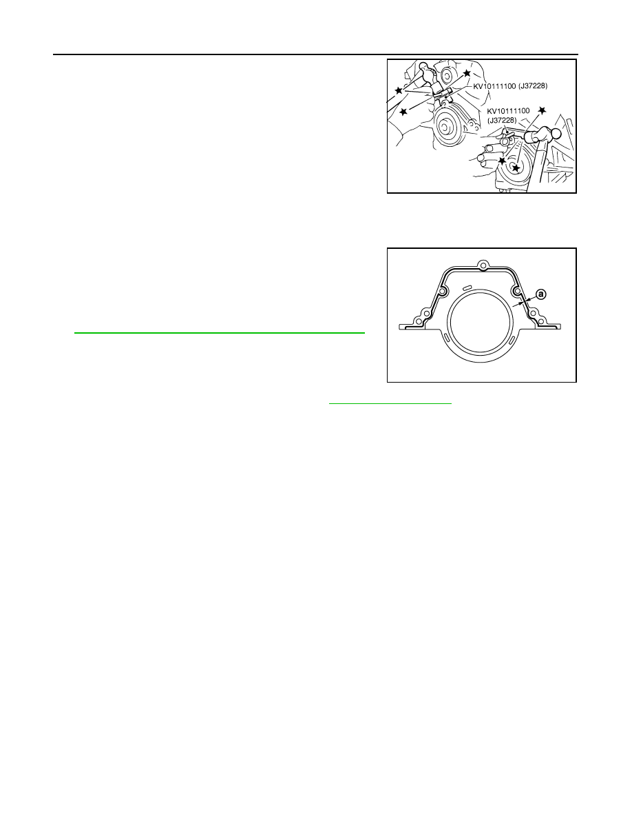
4.
Use a seal cutter (SST) to cut away liquid gasket and remove
rear oil seal retainer.
CAUTION:
Be careful not to damage mating surfaces.
NOTE:
Regard both rear oil seal and retainer an assembly.
INSTALLATION
1.
Remove old liquid gasket on mating surfaces of cylinder block and oil pan (upper) using scraper.
2.
Apply new engine oil to both oil seal lip and dust seal lip of new oil seal retainer.
3.
Apply a continuous bead of liquid gasket with the tube presser
(commercial service tool) to rear oil seal retainer as shown in the
figure.
Use Genuine RTV Silicone Sealant or equivalent. Refer to
GI-22, "Recommended Chemical Products and Sealants"
.
CAUTION:
Attaching should be done within 5 minutes after coating.
4.
Install rear oil seal retainer to cylinder block. Refer to
.
• Check the garter spring is in position and seal lips not inverted.
5.
Install in the reverse order of removal after this step.
SEM830E
a
:
φ
2.0 - 3.0 mm (0.08 - 0.12 in)
JPBIA0542ZZ