содержание .. 629 630 631 632 ..
Nissan Murano. Manual - part 631
EM-98
< UNIT DISASSEMBLY AND ASSEMBLY >
CAMSHAFT
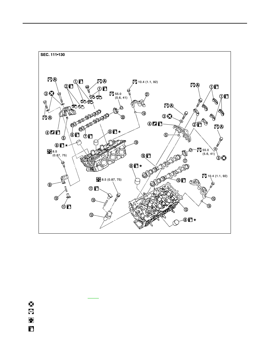
CAMSHAFT
Exploded View
INFOID:0000000009717996
1.
Camshaft bracket (No. 3, 4)
2.
Camshaft bracket (No. 2)
3.
Seal washer
4.
Camshaft bracket (No. 1)
5.
Dowel pin
6.
Camshaft (EXH) (bank 1)
7.
Camshaft (INT) (bank 1)
8.
Valve lifter
9.
Timing chain tensioner (secondary)
(bank 1)
10. Spring
11.
Plunger
12.
Timing chain tensioner (secondary)
(bank 2)
13. Cylinder head (bank 2)
14.
Dowel pin
15. Camshaft sensor bracket (bank 2)
16. Camshaft (EXH) (bank 2)
17.
Camshaft signal plate (bank 2)
18. Camshaft (INT) (bank 2)
19. Cylinder head (bank 1)
20.
Camshaft signal plate (bank 1)
21. Camshaft sensor bracket (bank 1)
A.
Comply with the installation proce-
dure when tightening. Refer to
: Always replace after every disassembly.
: N·m (kg-m, ft-lb)
: N·m (kg-m, in-lb)
: Should be lubricated with oil.
JPBIA1719GB