содержание .. 588 589 590 591 ..
Nissan Murano. Manual - part 590
EC-470
< DTC/CIRCUIT DIAGNOSIS >
[VQ35DE]
VARIABLE INDUCTION AIR SYSTEM
Without CONSULT
1.
Stop engine and disconnect vacuum hose connected to power valve actuator 1.
2.
Disconnect VIAS control solenoid valve 1 harness connector.
3.
Start engine.
4.
Rev engine quickly up to approximately 5,000 rpm.
5.
Check vacuum existence under the following conditions.
Is the inspection result normal?
YES
>> Repair or replace power valve actuator 1. Refer to
EC-36, "Component Parts Location"
NO
>> GO TO 3.
3.
CHECK VACUUM TANK
1.
Stop engine and disconnect vacuum hose connected to intake manifold collector.
2.
Start engine and let it idle.
3.
Check vacuum existence from intake manifold collector.
Does vacuum existence from the intake manifold collector?
YES
>> GO TO 4.
NO
>> Replace intake manifold collector. Refer to
.
4.
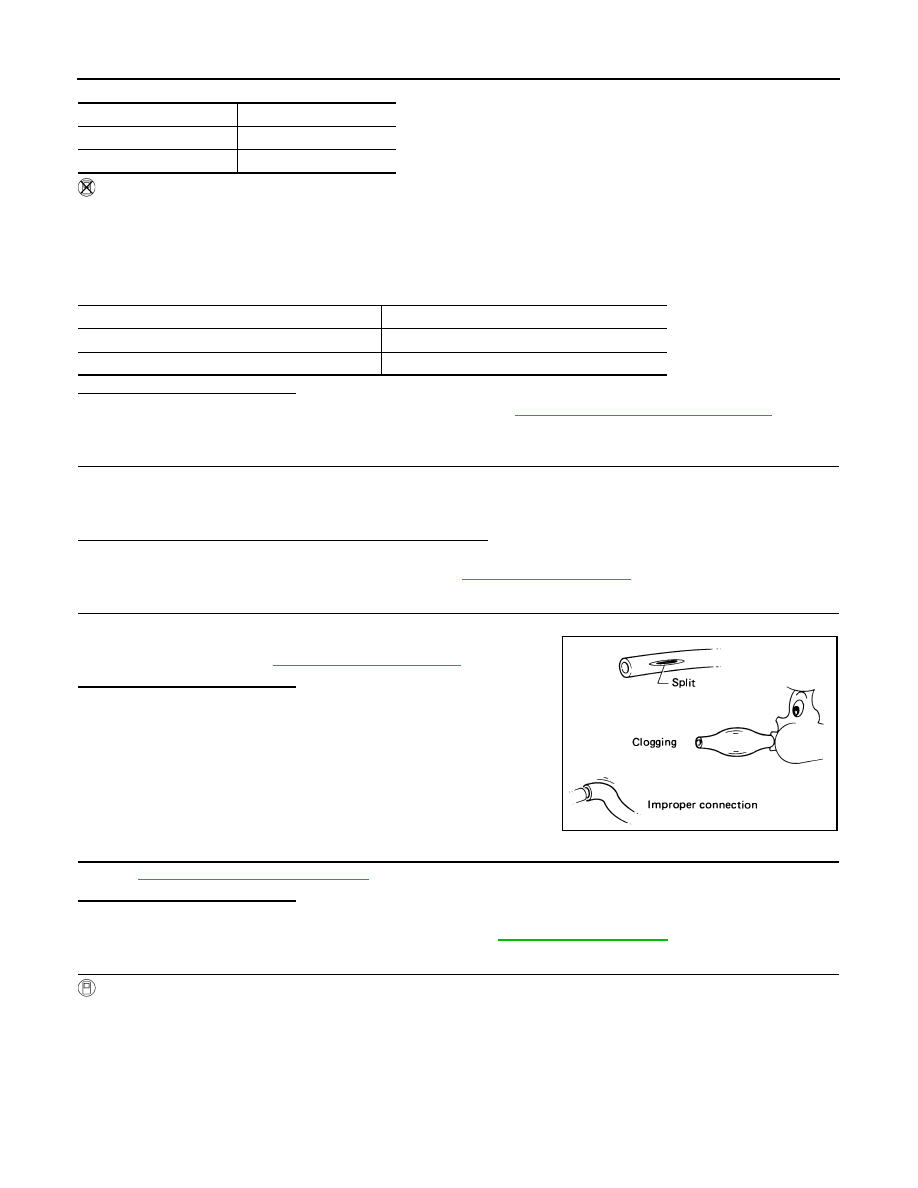
CHECK VACUUM HOSE
1.
Stop engine.
2.
Check vacuum hose for crack, clogging, improper connection or
disconnection. Refer to
Is the inspection result normal?
YES
>> GO TO 5.
NO
>> Repair hoses or tubes.
5.
CHECK VIAS CONTROL SOLENOID VALVE 1
EC-395, "Component Inspection"
Is the inspection result normal?
YES
>> GO TO 9.
NO
>> Replace VIAS control solenoid valve 1. Refer to
.
6.
CHECK VACUUM EXISTENCE-II
With CONSULT
1.
Stop engine and disconnect vacuum hose connected to power valve actuator 2.
2.
Start engine and let it idle.
3.
Perform “VIAS S/V-2” in “ACTIVE TEST” mode with CONSULT.
4.
Turn VIAS control solenoid valve 2 ON and OFF, and check vacuum existence under the following condi-
tions.
VIAS S/V-1
Vacuum
ON
Existed
OFF
Not existed
Condition
Vacuum
Idle
Existed
Rev engine quickly up to approximately 5,000 rpm
Not existed
SEF109L