содержание .. 463 464 465 466 ..
Nissan Murano. Manual - part 465
SIDE OIL SEAL
DLN-99
< REMOVAL AND INSTALLATION >
[REAR FINAL DRIVE: R145]
C
E
F
G
H
I
J
K
L
M
A
B
DLN
N
O
P
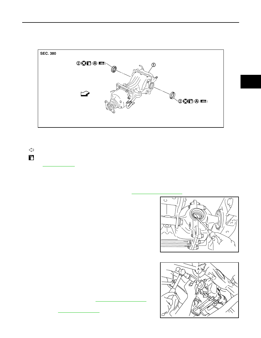
SIDE OIL SEAL
Exploded View
INFOID:0000000009718184
Removal and Installation
INFOID:0000000009718185
REMOVAL
1.
Remove rear drive shafts with power tool. Refer to
.
2.
Remove side oil seals, using a suitable tool.
CAUTION:
Be careful not to damage gear carrier and rear cover.
INSTALLATION
1.
Install side oil seals until it becomes flush with the carrier end,
using the drift (A) [SST: KV38100200 (J-26233)].
CAUTION:
• Never reuse oil seals.
• When installing, never incline oil seals.
• Apply multi-purpose grease onto oil seal lips, and gear oil
onto the circumference of oil seal.
2.
Install rear drive shafts. Refer to
3.
When oil leaks while removing, check oil level after the installa-
tion. Refer to
1.
Final drive assembly
2.
Side oil seal
A.
Oil seal lip
: Vehicle front
: Apply gear oil.
Refer to
for symbols not described above.
JSDIA0232ZZ
PDIA0431E
JPDID0183ZZ