содержание .. 455 456 457 458 ..
Nissan Murano. Manual - part 457
DRIVE PINION
DLN-67
< UNIT DISASSEMBLY AND ASSEMBLY >
[TRANSFER: TY20A]
C
E
F
G
H
I
J
K
L
M
A
B
DLN
N
O
P
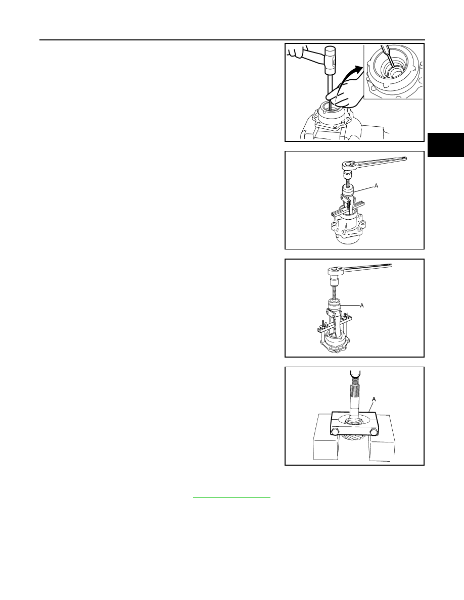
8.
Put out the circumference of pinion sleeve oil seal from back
side of pinion sleeve with punch to remove pinion sleeve oil
seal.
CAUTION:
When removing oil seal, never damage the pinion sleeve by
scooping it out with a tool.
9.
Remove pinion rear bearing inner race.
10. Remove the pinion rear bearing outer race with the puller (A)
[SST: KV381054S0 (J-34286)].
11. Remove the pinion front bearing outer race with the puller (A)
[SST: KV381054S0 (J-34286)].
12. Remove the collapsible spacer from the drive pinion.
13. Using the replacer (A) (commercial service tool), press the pin-
ion front bearing inner race out of the drive pinion.
Assembly
INFOID:0000000009718154
1.
Select the pinion sleeve shim. Refer to
JSDIA2345ZZ
JPDIE0026ZZ
JPDIE0027ZZ
JPDIE0028ZZ