содержание .. 454 455 456 457 ..
Nissan Murano. Manual - part 456
GEAR RING
DLN-63
< UNIT DISASSEMBLY AND ASSEMBLY >
[TRANSFER: TY20A]
C
E
F
G
H
I
J
K
L
M
A
B
DLN
N
O
P
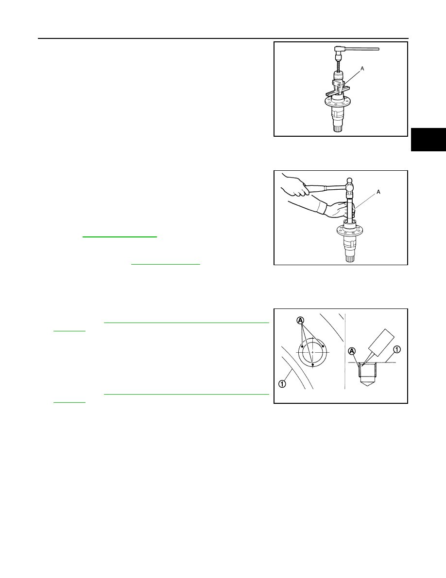
8.
Remove gear ring oil seal from the gear ring with a puller (A)
[SST: KV381054S0 (J-34286)].
Assembly
INFOID:0000000009718150
1.
Install gear ring oil seal to the gear ring with the drift (A) [SST: ST33230000 (J-25805-01)].
Apply multi-purpose grease onto oil seal lips, and gear oil onto
the circumference of the oil seal.
CAUTION:
• Never reuse the oil seal.
• The oil seal back position after the installation shall be
56.5 mm (2.224 in) from the gear ring end.
2.
Select gear ring bearing adjusting shim (transfer case side).
Refer to
3.
Assemble the selected gear ring adjusting shim (transfer case
side) and gear ring bearing outer race (transfer case side) to the
transfer case. Refer to
Apply gear oil to the gear ring bearing (transfer case side).
CAUTION:
Never reuse gear ring bearing (transfer case side).
4.
Apply thread locking sealant into the thread hole for the drive gear (1).
Use Genuine High Strength Thread Locking Sealant or equiva-
lent. Refer to
GI-22, "Recommended Chemical Products and
.
a.
Completely clean and degrease the drive gear back face, thread
holes, and drive gear mounting bolts.
b.
Apply thread locking sealant onto the first and second threads
under the thread hole chamfering of the drive gear on 3 or more
different points (A).
Use Genuine High Strength Thread Locking Sealant or equiva-
lent. Refer to
GI-22, "Recommended Chemical Products and
.
5.
Install the drive gear to gear ring, and apply anti-corrosive oil
onto threads and seats on the mounting bolts.
CAUTION:
If the thread locking sealant is applied aside, quickly wipe it off.
6.
The drive gear mounting bolts are tightened according to the following torque.
CAUTION:
Temporary installation before tightening the bolts through to the completion of the tightening
should be within 90 seconds.
JPDIE0032ZZ
JPDIE0037ZZ
1st step
: 27 N·m (2.8 kg-m, 20 ft-lb)
2nd step
: 98.5 N·m (10 kg-m, 73 ft-lb)
JPDIE0038ZZ