Nissan Murano. Manual - part 426


  Главная      Nissan     Nissan Murano (2014 year) - Service Manual


поиск по сайту            


содержание   ..  424  425  426  427   ..


Nissan Murano. Manual - part 426


RADIATOR CORE SUPPORT

DLK-315

< REMOVAL AND INSTALLATION >

[WITH INTELLIGENT KEY SYSTEM]

C

D

E

F

G

H

I

J

L

M

A

B

DLK

N

O

P

15. Remove radiator and engine coolant reservoir tank. Refer to 

CO-17, "Removal and Installation"

.

CAUTION:

Operate with two workers, because of it is heavy weight.

16. Disconnect connectors of the following parts.

• Ambient sensor. Refer to 

VTL-26, "Removal and Installation"

.

• Cooling fan (RH/LH) and cooling fan control module. Refer to 

CO-20, "Exploded View"

.

• Crash zone sensor. Refer to 

SR-22, "Removal and Installation"

.

17. Remove radiator upper hose from radiator core support. Refer to 

CO-16, "Exploded View"

.

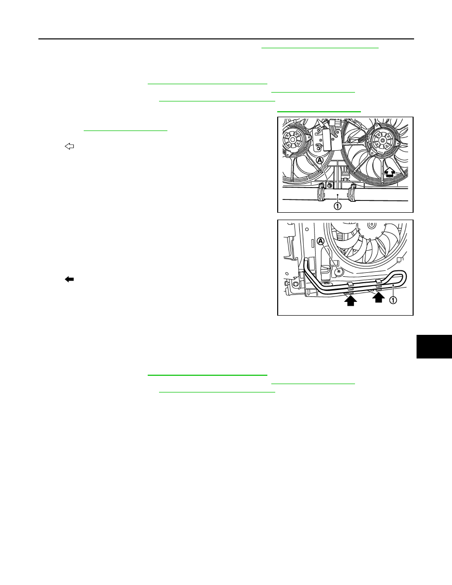
18. Remove mounting bolt (A) of radiator lower hose bracket (1).

Refer to 

CO-16, "Exploded View"

.

19. Remove radiator lower hose clamp (A) from radiator core sup-

port.

20. Remove power steering oil cooler pipe (1) from radiator core

support.

21. Remove power steering oil cooler pipe clips.  

22. Remove all harness clips from radiator core support.

23. Remove mounting bolts, and then remove radiator core support.

CAUTION:

Never damage power steering oil cooler pipe.

24. Remove the following parts after removing radiator core support.

• Ambient sensor. Refer to 

VTL-26, "Removal and Installation"

.

• Cooling fan (RH/LH) and cooling fan control module. Refer to 

CO-20, "Exploded View"

.

• Crash zone sensor. Refer to 

SR-22, "Removal and Installation"

.

INSTALLATION

Install in the reverse order of removal.

: Vehicle front

JMKIA1915ZZ

: Clip

JMKIA1916ZZ

DLK-316

< REMOVAL AND INSTALLATION >

[WITH INTELLIGENT KEY SYSTEM]

FRONT FENDER

FRONT FENDER

Exploded View

INFOID:0000000009719222

Removal and Installation

INFOID:0000000009719223

CAUTION:

Use a shop cloth to protect the body from being damaged during removal and installation.

REMOVAL

1.

Remove clips and remove front fender seal (front/rear).

2.

Remove front grille. Refer to 

EXT-21, "Removal and Installation"

.

3.

Remove front bumper fascia. Refer to 

EXT-15, "Removal and Installation"

.

4.

Remove front combination lamp. Refer to 

EXL-179, "Removal and Installation"

 (XENON TYPE), 

EXL-360,

"Removal and Installation"

 (HALOGEN TYPE).

5.

Remove fender protector. Refer to 

EXT-26, "FENDER PROTECTOR : Removal and Installation"

.

1.

Front fender seal (front)

2.

Front fender seal (rear)

3.

Front fender assembly

4.

Front fender finisher

5.

Insulator

: Clip

: Pawl

JMKIA1806ZZ

FRONT FENDER

DLK-317

< REMOVAL AND INSTALLATION >

[WITH INTELLIGENT KEY SYSTEM]

C

D

E

F

G

H

I

J

L

M

A

B

DLK

N

O

P

6.

Using remover tool (A), remove front fender finisher (1).

7.

Disengage front part of windshield glass molding from front fender.

8.

Remove mounting bolts and remove front fender.

CAUTION:

An viscous urethane foam is installed on the back surface of front fender. When removing the
front fender, peel of the urethane foam bit at a time, and carefully to remove it.

INSTALLATION

Install in the reverse order of removal.

CAUTION:

• After installation, check front fender adjustment. Refer to 

DLK-309, "HOOD ASSEMBLY : Adjust-

ment"

 and 

DLK-319, "DOOR ASSEMBLY : Adjustment"

.

• After installation, apply the touch-up paint (the body color) onto the head of front fender mounting

bolts.

: Clip

: Pawl

JMKIA2261ZZ

DLK-318

< REMOVAL AND INSTALLATION >

[WITH INTELLIGENT KEY SYSTEM]

FRONT DOOR

FRONT DOOR

DOOR ASSEMBLY

DOOR ASSEMBLY : Exploded View

INFOID:0000000009719224

DOOR ASSEMBLY : Removal and Installation

INFOID:0000000009719225

CAUTION:

• Perform work with 2 workers, because of its heavy weight.
• When removing and installing front door assembly, support door with a jack and shop cloth to pro-

tect door and body.

REMOVAL

1.

Remove mounting bolts of door check link on the vehicle.

2.

Remove front door harness grommet, and then pull out the harness from the vehicle.

3.

Disconnect front door harness connector.

4.

Remove door hinge mounting nuts (door side), and then remove door assembly.

INSTALLATION

Install in the reverse order of removal.

CAUTION:

• Check front door open/close, lock/unlock operation after installation.
• Check door hinge rotating part for poor lubrication. If necessary, apply body grease.
• After installation, perform the fitting adjustment. Refer to 

DLK-319, "DOOR ASSEMBLY : Adjust-

ment"

.

• After installation, apply touch-up paint (the body color) onto the head of door hinge mounting nuts.

1.

Front door panel

2.

Grommet

3.

Door striker

4.

TORX bolt

5.

Bumper rubber

6.

Door check link

7.

Door hinge (lower)

8.

Door hinge (upper)

Refer to 

GI-4, "Components"

 for symbols in the figure.

JMKIA3688ZZ


содержание   ..  424  425  426  427   ..