содержание .. 364 365 366 367 ..
Nissan Murano. Manual - part 366
B2417 TOUCH SENSOR LH
DLK-75
< DTC/CIRCUIT DIAGNOSIS >
[WITH INTELLIGENT KEY SYSTEM]
C
D
E
F
G
H
I
J
L
M
A
B
DLK
N
O
P
3.
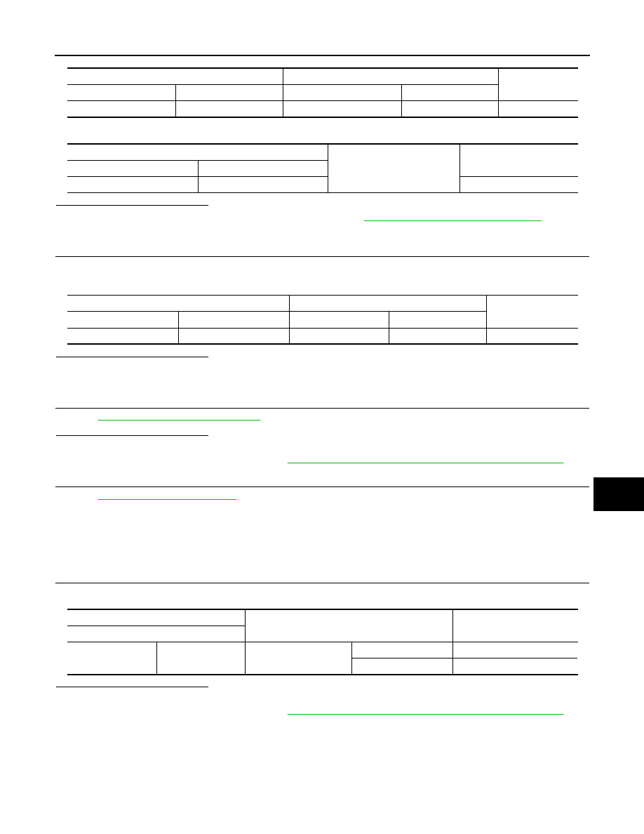
Check continuity between automatic back door control unit harness connector and ground.
Is the inspection result normal?
YES
>> Replace automatic back door control unit. Refer to
DLK-368, "Removal and Installation"
.
NO
>> Repair or replace harness.
4.
CHECK TOUCH SENSOR LH GROUND CIRCUIT
Check continuity between automatic back door control unit harness connector and touch sensor LH harness
connector.
Is the inspection result normal?
YES
>> GO TO 5.
NO
>> Repair or replace harness.
5.
CHECK TOUCH SENSOR LH
DLK-75, "Component Inspection"
Is the inspection result normal?
YES
>> GO TO 6.
NO
>> Replace touch sensor LH. Refer to
DLK-354, "TOUCH SENSOR : Removal and Installation"
.
6.
CHECK INTERMITTENT INCIDENT
GI-44, "Intermittent Incident"
.
>> INSPECTION END
Component Inspection
INFOID:0000000009718944
1.
CHECK TOUCH SENSOR LH
Check touch sensor LH.
Is the inspection result normal?
YES
>> INSPECTION END
NO
>> Replace touch sensor LH. Refer to
DLK-354, "TOUCH SENSOR : Removal and Installation"
.
Automatic back door control unit
Touch sensor LH
Continuity
Connector
Terminal
Connector
Terminal
B8
14
D165
1
Existed
Automatic back door control unit
Ground
Continuity
Connector
Terminal
B8
14
Not existed
Automatic back door control unit
Touch sensor LH
Continuity
Connector
Terminal
Connector
Terminal
B8
15
D165
2
Existed
Terminal
Condition
Resistance
(Approx.)
Touch sensor LH
1
2
Touch sensor LH
Detect obstruction
120
Ω
or less
Other than above
1 k
Ω
±
10%