Nissan Murano. Manual - part 321


  Главная      Nissan     Nissan Murano (2014 year) - Service Manual


поиск по сайту            


содержание   ..  319  320  321  322   ..


Nissan Murano. Manual - part 321


DAS-174

< DTC/CIRCUIT DIAGNOSIS >

[BSW]

WASHER SWITCHING SOLENOID VALVE CIRCUIT

WASHER SWITCHING SOLENOID VALVE CIRCUIT

Component Function Check

INFOID:0000000009723381

1.

CHECK WASHER SWITCHING SOLENOID VALVE CIRCUIT

1.

Turn the ignition switch ON.

2.

Select the ACTIVE TEST item “WASH ACTIVE” of “AVM” with CONSULT.

3.

With operating the test item, check the operation.

Is the inspection result normal?

YES

>> Washer switching solenoid valve circuit is normal.

NO

>> Refer to 

DAS-174, "Diagnosis Procedure"

.

Diagnosis Procedure

INFOID:0000000009723382

1.

CHECK WASHER SWITCHING SOLENOID VALVE POWER SUPPLY CIRCUIT

1.

Turn the ignition switch ON.

2.

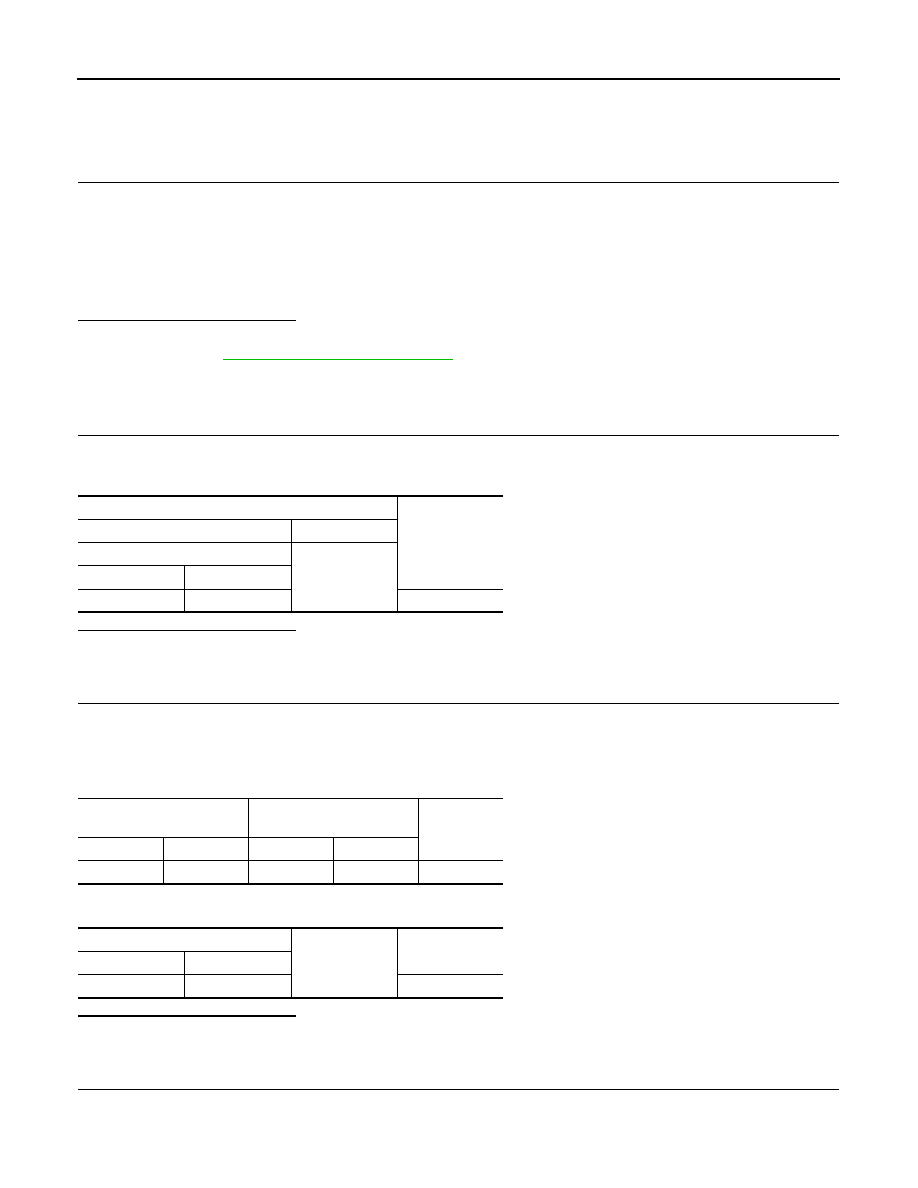
Check voltage between washer switching solenoid valve harness connector and ground.

Is the inspection result normal?

YES

>> GO TO 2.

NO

>> Repair washer switching solenoid valve power supply circuit.

2.

CHECK WASHER SWITCHING SOLENOID VALVE SIGNAL CIRCUIT

1.

Turn ignition switch OFF.

2.

Disconnect washer switching solenoid valve connector and pump control unit connector.

3.

Check continuity between washer switching solenoid valve harness connector and the pump control unit
harness connector.

4.

Check continuity between washer switching solenoid valve harness connector and the ground.

Is the inspection result normal?

YES

>> GO TO 3.

NO

>> Repair harness or connector.

3.

CHECK WASHER SWITCHING SOLENOID VALVE GROUND CIRCUIT

1.

Disconnect combination switch.

2.

Check continuity between washer switching solenoid valve harness connector and the combination switch
harness connector.

On

: Rear view camera washer is activated.

Off

: Rear view camera washer is not activated.

Terminals

Voltage

(Approx.)

(+)

(

)

Washer switching solenoid valve

Ground

Connector

Terminal

D167

2

Battery voltage

Washer switching solenoid 

valve

Pump control unit

Continuity

Connector

Terminal

Connector

Terminal

D167

3

D170

9

Existed

Washer switching solenoid valve

Ground

Continuity

Connector

Terminal

D167

3

Not existed

DAS

WASHER SWITCHING SOLENOID VALVE CIRCUIT

DAS-175

< DTC/CIRCUIT DIAGNOSIS >

[BSW]

C

D

E

F

G

H

I

J

K

L

M

B

N

P

A

Is the inspection result normal?

YES

>> Replace washer switching solenoid valve.

NO

>> Repair harness or connector.

Washer switching solenoid 

valve

Combination switch

Continuity

Connector

Terminal

Connector

Terminal

D167

3

M103

3

Existed

DAS-176

< DTC/CIRCUIT DIAGNOSIS >

[BSW]

REAR WASHER SWITCH INPUT SIGNAL CIRCUIT

REAR WASHER SWITCH INPUT SIGNAL CIRCUIT

Diagnosis Procedure

INFOID:0000000009723383

1.

CHECK COMBINATION SWITCH INPUT SIGNAL CIRCUIT

1.

Turn ignition switch OFF.

2.

Disconnect pump control unit connector and combination switch connector.

3.

Check continuity between combination switch harness connector and pump control unit harness connec-
tor.

4.

Check continuity between pump control unit harness connector and the ground.

Is the inspection result normal? 

YES

>> Replace pump control unit. Refer to 

DAS-189, "Removal and Installation"

.

NO

>> Repair harness or connector.

Terminals

Continuity

Pump control unit

Combination switch

Connector

Terminal

Connector

Terminal

D170

10

M103

1

Existed

Pump control unit

Ground

Continuity

Connector

Terminal

D170

10

Not existed

DAS

WASHER LEVEL SWITCH SIGNAL CIRCUIT

DAS-177

< DTC/CIRCUIT DIAGNOSIS >

[BSW]

C

D

E

F

G

H

I

J

K

L

M

B

N

P

A

WASHER LEVEL SWITCH SIGNAL CIRCUIT

Diagnosis Procedure

INFOID:0000000009723384

1.

CHECK WASHER LEVEL SWITCH INPUT SIGNAL CIRCUIT

1.

Turn ignition switch OFF.

2.

Disconnect combination meter connector and camera control unit.

3.

Check continuity between combination meter harness connector and camera control unit harness connec-
tor.

4.

Disconnect washer level switch harness connector.

5.

Check continuity between camera control unit harness connector and the ground.

Is the inspection result normal? 

YES

>> GO TO 2.

NO

>> Repair harness or connector.

2.

CHECK WASHER LEVEL SWITCH SIGNAL CIRCUIT

Check washer level switch signal circuit. Refer to 

MWI-49, "Diagnosis Procedure"

.

Is the inspection result normal? 

YES

>> GO TO 3.

NO

>> Repair harness or connector.

3.

CHECK WASHER LEVEL SWITCH

Perform a unit check for the washer level switch. Refer to 

MWI-50, "Component Inspection"

.

Is the inspection result normal? 

YES

>> Replace camera control unit. Refer to 

DAS-187, "Removal and Installation"

.

NO

>> Replace washer tank. Refer to 

WW-128, "Removal and Installation"

.

Combination meter

Camera control unit

Continuity

Connector

Terminal

Connector

Terminal

M34

29

B93

40

Existed

Camera control unit

Ground

Continuity

Connector

Terminal

B93

40

Not existed


содержание   ..  319  320  321  322   ..