Nissan Murano. Manual - part 319


  Главная      Nissan     Nissan Murano (2014 year) - Service Manual


поиск по сайту            


содержание   ..  317  318  319  320   ..


Nissan Murano. Manual - part 319


DAS-166

< DTC/CIRCUIT DIAGNOSIS >

[BSW]

POWER SUPPLY AND GROUND CIRCUIT

YES

>> GO TO 2.

NO

>> Be sure to eliminate cause of malfunction before installing new fuse. 

2.

CHECK PUMP CONTROL UNIT POWER SUPPLY CIRCUIT 

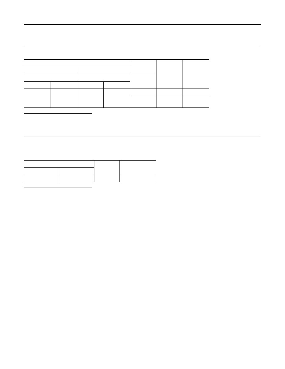
Check voltage between pump control unit harness connector and ground. 

Is the inspection result normal?

YES

>> GO TO 3.

NO

>> Repair the pump control unit power supply circuit. 

3.

CHECK PUMP CONTROL UNIT GROUND CIRCUIT

1.

Turn the ignition switch OFF.

2.

Disconnect the pump control unit connector. 

3.

Check for continuity between pump control unit harness connector and ground. 

Is the inspection result normal?

YES

>> INSPECTION END

NO

>> Repair the pump control unit ground circuit.

Terminal

Condition

Standard 

voltage

Reference 

voltage

(+)

(–)

Pump control unit

Ignition 

switch

Connector

Terminal

Connector

Terminal

D170

12

D170

5

OFF

0 - 0.1 V

0 V

ON

9.5 - 16 V

Battery volt-

age

Pump control unit

Ground

Continuity

Connector

Terminal

D170

5

Existed

DAS

WARNING SYSTEMS SWITCH CIRCUIT

DAS-167

< DTC/CIRCUIT DIAGNOSIS >

[BSW]

C

D

E

F

G

H

I

J

K

L

M

B

N

P

A

WARNING SYSTEMS SWITCH CIRCUIT

Component Function Check

INFOID:0000000009723372

1.

CHECK WARNING SYSTEMS SWITCH INPUT SIGNAL

1.

Turn the ignition switch ON.

2.

Select the DATA MONITOR item “ITS SW 1” of “AVM” with CONSULT.

3.

With operating the warning systems switch, check the monitor status.

Is the inspection result normal?

YES

>> Warning systems switch circuit is normal.

NO

>> Refer to 

DAS-167, "Diagnosis Procedure"

.

Diagnosis Procedure

INFOID:0000000009723373

1.

CHECK WARNING SYSTEMS SWITCH SIGNAL INPUT

1.

Turn the ignition switch ON.

2.

Check voltage between camera control unit harness connector and ground.

Is the inspection result normal?

YES

>> Replace the camera control unit. Refer to 

DAS-187, "Removal and Installation"

.

NO

>> GO TO 2.

2.

CHECK WARNING SYSTEMS SWITCH

1.

Turn ignition switch OFF.

2.

Remove warning systems switch.

3.

Check warning systems switch. Refer to 

DAS-194, "Removal and Installation"

.

Is the inspection result normal?

YES

>> GO TO 3.

NO

>> Replace the warning systems switch. Refer to 

DAS-194, "Removal and Installation"

.

3.

CHECK WARNING SYSTEMS SWITCH GROUND CIRCUIT

Check continuity between warning systems switch harness connector and the ground.

Is the inspection result normal?

YES

>> GO TO 4.

NO

>> Repair harness or connector.

4.

CHECK WARNING SYSTEMS SWITCH SIGNAL INPUT CIRCUIT FOR OPEN

1.

Disconnect the camera control unit connector.

Monitor item

Condition

Monitor status

ITS SW 1

Warning systems switch is pressed

On

Warning systems switch is not pressed

OFF

Terminals

Condition

Standard 

voltage

Reference 

voltage

(+)

(

)

Camera control unit

Ground

Warning 
systems 

switch

Connector

Terminal

B92

17

Pressed

0 - 0.1 V

0 V

Released

9.5 - 16 V

12 V

Warning systems switch 

Ground

Continuity

Connector

Terminal

M39

6

Existed

DAS-168

< DTC/CIRCUIT DIAGNOSIS >

[BSW]

WARNING SYSTEMS SWITCH CIRCUIT

2.

Check continuity between the camera control unit harness connector and warning systems switch har-
ness connector.

Is the inspection result normal?

YES

>> GO TO 5.

NO

>> Repair the harnesses or connectors.

5.

CHECK WARNING SYSTEMS SWITCH SIGNAL INPUT CIRCUIT FOR SHORT

Check continuity between the camera control unit harness connector and ground.

Is the inspection result normal?

YES

>> Replace the camera control unit. Refer to 

DAS-187, "Removal and Installation"

.

NO

>> Repair the harnesses or connectors.

Component Inspection

INFOID:0000000009723374

1.

CHECK WARNING SYSTEMS SWITCH

Check continuity of warning systems switch.

Is the inspection result normal?

YES

>> INSPECTION END

NO

>> Replace warning systems switch.

Camera control unit

Warning systems switch

Continuity

Connector

Terminal

Connector

Terminal

B92

17

M39

7

Existed

Camera control unit

Ground

Continuity

Connector

Terminal

B92

17

Not existed

Terminal

Condition

Continuity

7

9

When warning systems switch is pressed

Existed

When warning systems switch is released

Not existed

DAS

WARNING SYSTEMS ON INDICATOR CIRCUIT

DAS-169

< DTC/CIRCUIT DIAGNOSIS >

[BSW]

C

D

E

F

G

H

I

J

K

L

M

B

N

P

A

WARNING SYSTEMS ON INDICATOR CIRCUIT

Component Function Check

INFOID:0000000009723375

1.

CHECK WARNING SYSTEMS ON INDICATOR

1.

Turn the ignition switch ON.

2.

Select the ACTIVE TEST item “ITS SW 1 IND” of “AVM” with CONSULT.

3.

With operating the test item, check the operation.

Is the inspection result normal?

YES

>> Warning systems switch indicator circuit is normal.

NO

>> Refer to 

DAS-169, "Diagnosis Procedure"

.

Diagnosis Procedure

INFOID:0000000009723376

1.

CHECK WARNING ON INDICATOR POWER SUPPLY CIRCUIT

1.

Turn ignition switch OFF.

2.

Disconnect warning systems switch connector.

3.

Check voltage between warning systems switch harness connector and ground.

Is the inspection result normal?

YES

>> GO TO 2.

NO

>> Repair the warning systems ON indicator power supply circuit.

2.

CHECK WARNING SYSTEMS ON INDICATOR SIGNAL FOR OPEN

1.

Disconnect the camera control unit harness connector.

2.

Check continuity between the camera control unit harness connector and warning systems switch har-
ness connector.

Is the inspection result normal?

YES

>> GO TO 3.

NO

>> Repair the harnesses or connectors.

3.

CHECK WARNING SYSTEMS ON INDICATOR SIGNAL CIRCUIT FOR SHORT

Check continuity between the camera control unit harness connector and ground.

Is the inspection result normal?

YES

>> GO TO 4.

NO

>> Repair the harnesses or connectors.

On

: Warning systems ON indicator illuminates

Off

: Warning systems ON indicator is turned OFF

Terminals

Voltage

(Approx.)

(+)

(

)

Warning systems switch

Ground

Connector

Terminal

M39

3

Battery voltage

Camera control unit

Warning systems switch

Continuity

Connector

Terminal

Connector

Terminal

B92

15

M39

2

Existed

Camera control unit

Ground

Continuity

Connector

Terminal

B92

15

Not existed


содержание   ..  317  318  319  320   ..