содержание .. 279 280 281 282 ..
Nissan Murano. Manual - part 281
DAS-14
< SYSTEM DESCRIPTION >
[LDW]
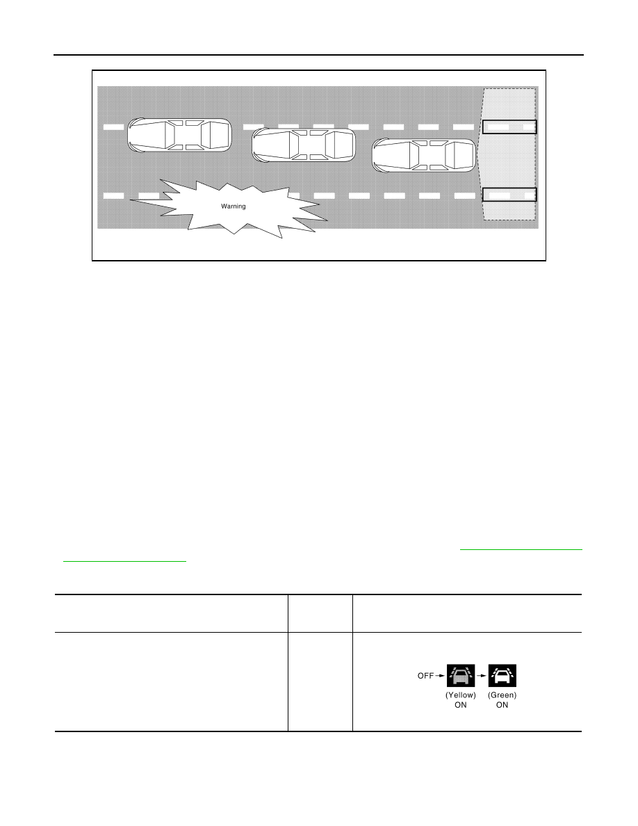
SYSTEM
EXAMPLE
When the vehicle approaches the right lane marker, the driver is alerted by the buzzer and the blinking of lane
departure warning lamp (yellow).
OPERATION DESCRIPTION
• When the system is turned ON by operating the warning systems switch, camera control unit turns ON the
LDW ON indicator lamp and the warning systems ON indicator.
• Rear view camera monitors the traveling lane. It transmits the camera image signal to camera control unit.
• When judging from a camera image signal that the vehicle is approaching the lane marker, the camera con-
trol unit controls the following item to alert the driver.
- Activates warning buzzer in the combination meter.
- Camera control unit transmits a lane departure warning lamp signal to combination meter via CAN communi-
cation and turns ON/OFF the lane departure warning lamp (yellow).
Operating Condition
• LDW ON indicator lamp: ON
• Warning systems ON indicator: ON
• Vehicle speed: approximately 70 km/h (45 MPH) or more
• Turn indicator signal: After 2 seconds or more from turned OFF
• Back door: Close
• Low washer fluid warning: OFF
NOTE:
• When the LDW system setting on the navigation screen is ON.
• After the operating conditions of warning are satisfied, the warning continues until the vehicle speed reaches
approximately 60 km/h (40 MPH)
• The LDW system may not function properly, depending on the situation. Refer to
Bulb Check Action and Fail-safe Indication
JSOIA0637GB
Vehicle condition/ Driver's operation
Warning sys-
tems ON indi-
cator
Indication on the combination meter
Ignition switch
OFF
⇒
ON
(Bulb check)
Approx. 5 sec.
ON
JSOIA0667GB