содержание .. 278 279 280 281 ..
Nissan Murano. Manual - part 280
DAS-10
< SYSTEM DESCRIPTION >
[LDW]
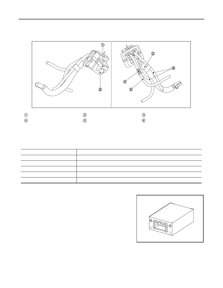
COMPONENT PARTS
• Power for the camera is supplied from the camera control unit, and the image at the rear of the vehicle is
sent to the camera control unit.
• The rear view camera is equipped with a washer nozzle and air nozzle for cleaning camera. A check valve is
installed to the tube connected to the washer nozzle.
NOTE:
*: “CMOS” is abbreviation of Complementary Metal Oxide Semiconductor, and features low power consump-
tion and high speed reading rate of electric charge.
Camera Specification
Pump Control Unit
INFOID:0000000009723206
• Pump control unit is installed in under the luggage floor front fin-
isher.
• Communicates with camera control unit via communication line.
• Activates air pump and washer pump according to the signal from camera control unit.
• Receives rear washer signal from washer switching solenoid valve.
Washer/Air nozzle
Rear view camera
Harness
Check valve
Washer tube
Air tube
JSOIA0647ZZ
Manufacturer name
SONY Corp.
Image pickup element
1/4-inch CMOS image sensor
Effective number of pixels
Approx. 300,000 pixels (632
×
480)
Minimum brightness
2 lx
Angle of view
H: 190.4
°
V: 141.8
°
Image
With mirror processing function
JSOIA0658ZZ