содержание .. 275 276 277 278 ..
Nissan Murano. Manual - part 277
WATER OUTLET AND WATER PIPING
CO-29
< REMOVAL AND INSTALLATION >
C
D
E
F
G
H
I
J
K
L
M
A
CO
N
P
O
WATER OUTLET AND WATER PIPING
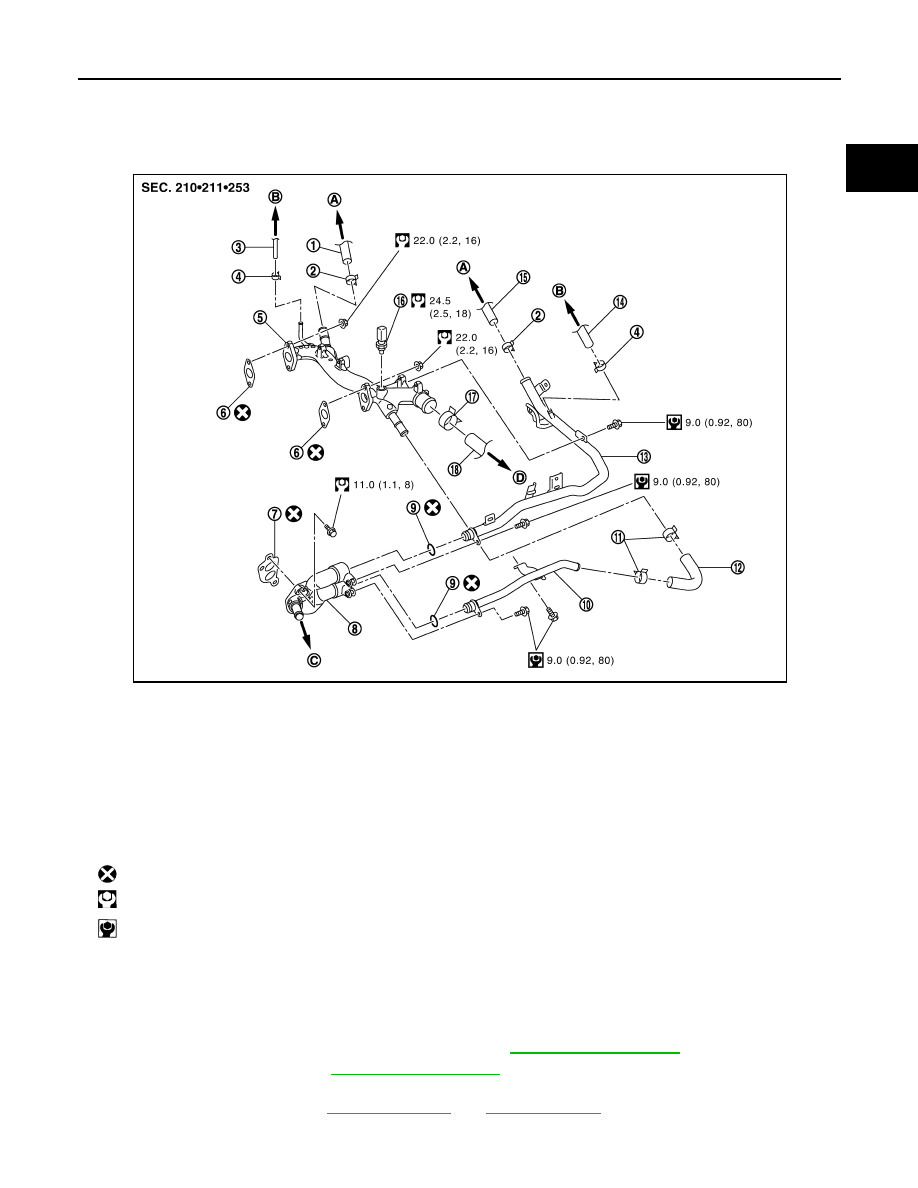
Exploded View
INFOID:0000000009720495
Removal and Installation
INFOID:0000000009720496
REMOVAL
1.
Remove air duct (inlet), radiator core support covers (RH and LH), air cleaner cases (upper and lower)
with mass air flow sensor and air duct assembly. Refer to
2.
Remove engine cover. Refer to
.
3.
Drain engine coolant from radiator drain plug at the bottom of radiator, and from water drain plug at the
front of cylinder block. Refer to
CAUTION:
1.
Heater hose
2.
Clamp
3.
Water hose
4.
Clamp
5.
Water outlet
6.
Gasket
7.
Gasket
8.
Water connector
9.
O-ring
10. Water bypass pipe
11.
Clamp
12.
Water hose
13. Heater pipe
14.
Water hose
15.
Heater hose
16. Engine coolant temperature sensor
17.
Clamp
18.
Radiator hose (upper)
A.
To heater core
B.
To electric throttle control actuator
C.
To oil cooler
D.
To radiator
: Always replace after every disassembly.
: N·m (kg-m, ft-lb)
: N·m (kg-m, in-lb)
JPBIA1691GB