Nissan Murano. Manual - part 276


  Главная      Nissan     Nissan Murano (2014 year) - Service Manual


поиск по сайту            


содержание   ..  274  275  276  277   ..


Nissan Murano. Manual - part 276


WATER PUMP

CO-25

< REMOVAL AND INSTALLATION >

C

D

E

F

G

H

I

J

K

L

M

A

CO

N

P

O

a.

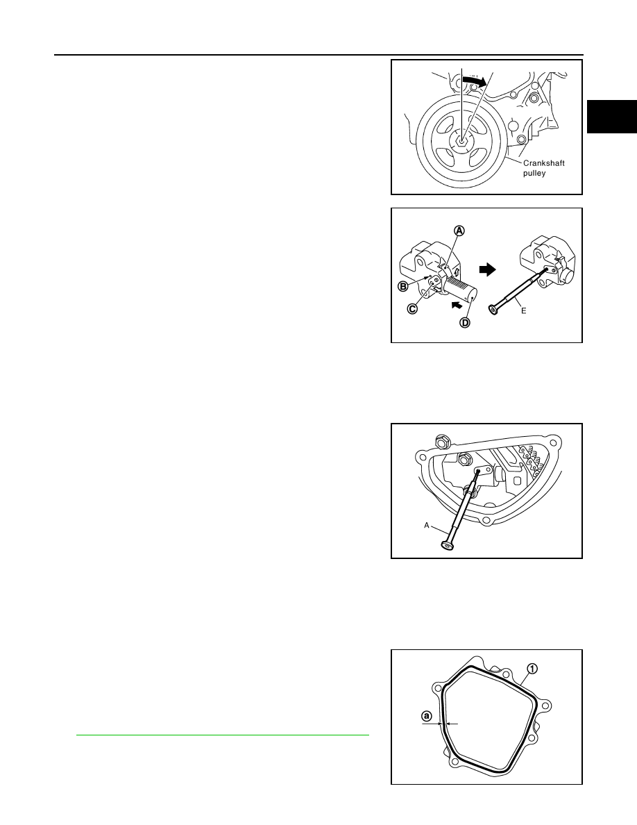
Turn crankshaft pulley clockwise so that timing chain on the tim-
ing chain tensioner (primary) side is loose.

b.

Pull plunger stopper tab (A) up (or turn lever downward) so as to
remove plunger stopper tab from the ratchet of plunger (D).
NOTE:
Plunger stopper tab and lever (C) are synchronized.

c.

Push plunger into the inside of tensioner body.

d.

Hold plunger in the fully compressed position by engaging
plunger stopper tab with the tip of ratchet.

e.

To secure lever, insert stopper pin (E) through hole of lever into
tensioner body hole (B).
• The lever parts and the tab are synchronized. Therefore, the

plunger will be secured under this condition.

NOTE:
Figure shows the example of 1.2 mm (0.047 in) diameter thin screwdriver being used as the stopper pin.

f.

Install timing chain tensioner (primary).
• Remove dust and foreign material completely from backside of timing chain tensioner (primary) and

from installation area of rear timing chain case.

g.

Remove stopper pin (A).

h.

Check again that timing chain and water pump sprocket are engaged.

4.

Install valve timing control cover (bank 1) and water pump cover as follows:

a.

Before installing, remove all traces of old liquid gasket from mating surface of water pump cover using
scraper. Also remove traces of old liquid gasket from the mating surface of front timing chain case.

b.

Apply a continuous bead of liquid gasket with the tube presser
(commercial service tool) to mating surface of water pump cover
(1).

Use Genuine RTV Silicone Sealant or equivalent. Refer to

GI-22, "Recommended Chemical Products and Sealants"

.

CAUTION:

Attaching should be done within 5 minutes after coating.

c.

Tighten mounting bolts.

PBIC4820E

JPBIA0118ZZ

JPBIA1774ZZ

a

φ

2.3 - 3.3 mm (0.091 - 0.130 in)

JPBIA1722ZZ

CO-26

< REMOVAL AND INSTALLATION >

WATER PUMP

5.

Install water drain plug (front) on water pump side of cylinder block.
• Apply liquid gasket to the thread of water drain plug (front).

Use Genuine RTV Silicone Sealant or equivalent. Refer to 

GI-22, "Recommended Chemical Prod-

ucts and Sealants"

.

6.

Install in the reverse order of removal after this step.
• After starting engine, let idle for three minutes, then rev engine up to 3,000 rpm under no load to

purge air from the high-pressure chamber of chain tensioner. Engine may produce a rattling
noise. This indicates that air still remains in the chamber and is not a matter of concern.

Inspection

INFOID:0000000009720491

INSPECTION AFTER REMOVAL

• Check for badly rusted or corroded water pump body assembly.
• Check for rough operation due to excessive end play.
• If anything is found, replace water pump.

INSPECTION AFTER INSTALLATION

• Check for leakage of engine coolant using the radiator cap tester adapter (commercial service tool) and the

radiator cap tester (commercial service tool). Refer to 

CO-11, "Inspection"

.

• Start and warm up the engine. Visually check that there is no leakage of engine coolant.

SLC943A

WATER INLET AND THERMOSTAT ASSEMBLY

CO-27

< REMOVAL AND INSTALLATION >

C

D

E

F

G

H

I

J

K

L

M

A

CO

N

P

O

WATER INLET AND THERMOSTAT ASSEMBLY

Exploded View

INFOID:0000000009720492

Removal and Installation

INFOID:0000000009720493

REMOVAL

1.

Drain engine coolant from radiator drain plug at the bottom of radiator, and from water drain plug at the
front of cylinder block. Refer to 

CO-11, "Draining"

 and 

EM-90, "Setting"

.

CAUTION:

• Perform this step when the engine is cold.
• Never spill engine coolant on drive belt.

2.

Remove reservoir tank of radiator, and move it aside. Refer to 

CO-16, "Exploded View"

.

3.

Remove intake valve timing control solenoid valve (bank 2). Refer to

EM-57, "Exploded View"

.

4.

Disconnect radiator hose (lower) from water inlet and thermostat assembly.

5.

Remove water inlet and thermostat assembly (1).

CAUTION:

Never disassemble water inlet and thermostat assembly.
Replace them as a unit, if necessary.

INSTALLATION

Note the following, and install in the reverse order of removal.
• Be careful not to spill engine coolant over engine room. Use rag to absorb engine coolant.

1.

Gasket

2.

Water inlet and thermostat assembly

3.

Clamp

4.

Radiator hose (lower)

A.

To radiator

: Always replace after every disassembly.

: N·m (kg-m, in-lb)

JPBIA1688GB

A

: Never loosen these screw

JPBIA0261ZZ

CO-28

< REMOVAL AND INSTALLATION >

WATER INLET AND THERMOSTAT ASSEMBLY

Inspection

INFOID:0000000009720494

INSPECTION AFTER REMOVAL

1.

Check valve seating condition at ordinary room temperatures. It should seat tightly.

2.

Check valve operation.

• If the malfunctioning condition, when valve seating at ordinary

room temperature, or measured values are out of the standard,
replace water inlet and thermostat assembly.

INSPECTION AFTER INSTALLATION

• Check for leakage of engine coolant using the radiator cap tester adapter (commercial service tool) and the

radiator cap tester (commercial service tool). Refer to 

CO-11, "Inspection"

.

• Start and warm up the engine. Visually check that there is no leakage of engine coolant.

Thermostat (Standard)

: Refer to 

CO-31, "Thermostat"

.

SLC949A


содержание   ..  274  275  276  277   ..