содержание .. 262 263 264 265 ..
Nissan Murano. Manual - part 264
CHG-12
< SYSTEM DESCRIPTION >
POWER GENERATION VOLTAGE VARIABLE CONTROL SYSTEM
POWER GENERATION VOLTAGE VARIABLE CONTROL SYSTEM
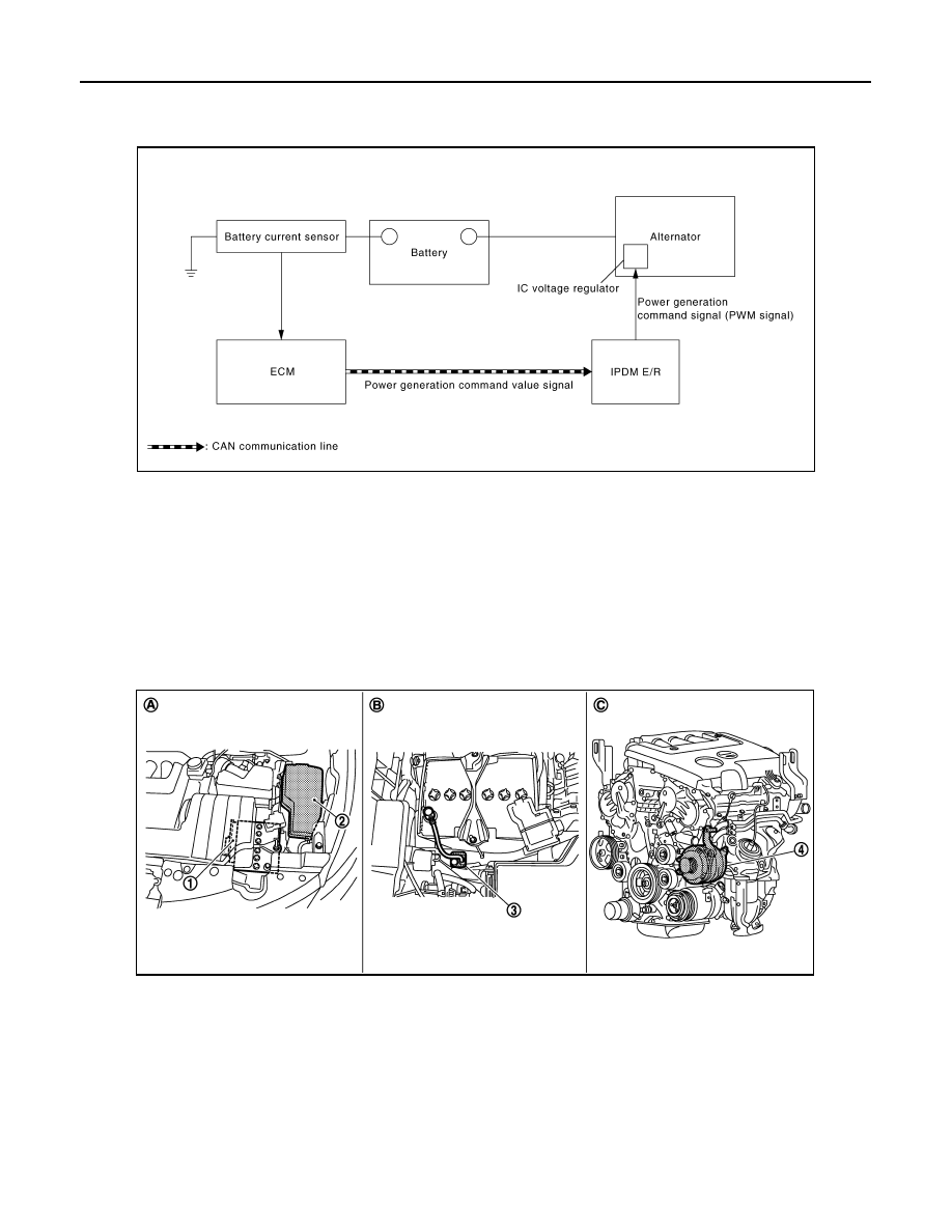
System Diagram
INFOID:0000000009722543
System Description
INFOID:0000000009722544
By performing the power generation voltage variable control, the engine load due to the power generation of
the alternator is reduced and fuel consumption is decreased.
NOTE:
When any malfunction is detected in the power generation voltage variable control system, the power genera-
tion is performed according to the characteristic of the IC voltage regulator of the alternator.
Component Parts Location
INFOID:0000000009722545
JMMIA1072GB
1.
ECM
2.
IPDM E/R
3.
Battery current sensor
4.
Alternator
A.
Engine room dash panel (LH)
B.
Battery
C.
Cylinder block left side
JPLIA0888ZZ