Nissan Murano. Manual - part 243


  Главная      Nissan     Nissan Murano (2014 year) - Service Manual


поиск по сайту            


содержание   ..  241  242  243  244   ..


Nissan Murano. Manual - part 243


BRC-128

< REMOVAL AND INSTALLATION >

[VDC/TCS/ABS]

ABS ACTUATOR AND ELECTRIC UNIT (CONTROL UNIT)

• To remove brake tube, use a flare nut wrench to prevent flare nuts and brake tube from being damaged. To

install, use flare nut crowfoot and torque wrench.

• Never apply excessive impact to ABS actuator and electric unit (control unit), such as dropping it.
• Never remove and install actuator by holding harness.
• After work is completed, bleed air from brake tube. Refer to 

BR-13, "Bleeding Brake System"

.

• After installing harness connector in the ABS actuator and electric unit (control unit), make sure harness

connector is securely locked. 

• After removing an ABS actuator and electric unit (control unit), be sure to perform the following procedure.
- Calibration of decel G sensor: Refer to 

BRC-10, "CALIBRATION OF DECEL G SENSOR : Description"

.

• After replacing an ABS actuator and electric unit (control unit), be sure to perform the following procedure.
- Adjustment of steering angle sensor neutral position: Refer to 

BRC-9, "ADJUSTMENT OF STEERING

ANGLE SENSOR NEUTRAL POSITION : Description"

.

- Calibration of decel G sensor: Refer to 

BRC-10, "CALIBRATION OF DECEL G SENSOR : Description"

.

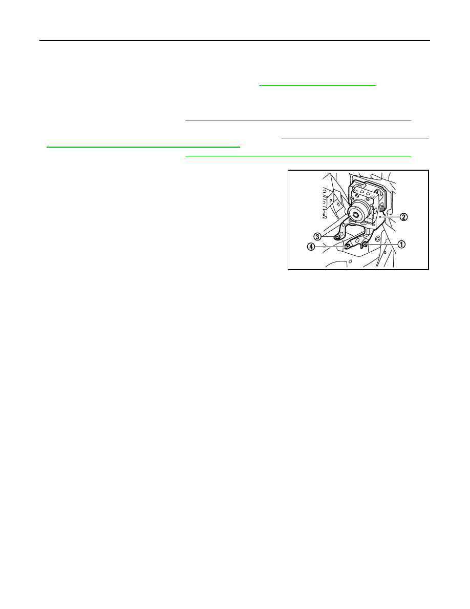
Install ABS actuator and electric unit (control unit) as per the following steps.

1.

Temporarily tighten mounting bolt (1) because the bracket (2) is
temporarily being hold.

2.

Tighten mounting bolt (3) while holding the bracket.

3.

Tighten mounting bolts to the specified torque in the order of (4),
(1).

JSFIA0400ZZ

YAW RATE/SIDE/DECEL G SENSOR

BRC-129

< REMOVAL AND INSTALLATION >

[VDC/TCS/ABS]

C

D

E

G

H

I

J

K

L

M

A

B

BRC

N

O

P

YAW RATE/SIDE/DECEL G SENSOR

Exploded View

INFOID:0000000009718388

Removal and Installation

INFOID:0000000009718389

REMOVAL

CAUTION:

Never drop or strike yaw rate/side/decel G sensor, or never use power tool etc., because yaw rate/side/
decel G sensor is sensitive to the impact.

1.

Remove center console assembly. Refer to 

IP-22, "Exploded View"

.

2.

Remove rear ventilator duct. Refer to 

VTL-59, "REAR VENTILATOR DUCT 2 : Exploded View"

 (without 7

inch display), 

VTL-123, "REAR VENTILATOR DUCT 2 : Exploded View"

 (with 7 inch display).

3.

Disconnect yaw rate/side/decel G sensor harness connector.

4.

Remove mounting nuts.

5.

Remove yaw rate/side/decel G sensor.

INSTALLATION

Note the following, and install in the reverse order of removal.
• Never drop or strike yaw rate/side/decel G sensor, or never use power tool etc., because yaw rate/side/decel

G sensor is sensitive to the impact.

• After removing/replacing a yaw rate/side/decel G sensor, be sure to perform the calibration of decel G sen-

sor. Refer to 

BRC-10, "CALIBRATION OF DECEL G SENSOR : Description"

.

1.

Yaw rate/side/decel G sensor

2.

Connector

: Vehicle front

Refer to 

GI-4, "Components"

 for symbol in the figure.

JPFIC0113GB

BRC-130

< REMOVAL AND INSTALLATION >

[VDC/TCS/ABS]

STEERING ANGLE SENSOR

STEERING ANGLE SENSOR

Exploded View

INFOID:0000000009718390

Removal and Installation

INFOID:0000000009718391

REMOVAL

1.

Remove spiral cable assembly. Refer to 

SR-15, "Exploded View"

.

2.

Remove steering angle sensor from spiral cable assembly.

INSTALLATION

Note the following, and install in the reverse order of removal.
• Never reuse steering angle sensor.
• After removing/replacing a steering angle sensor, be sure to perform the adjustment of steering angle sensor

neutral position. Refer to 

BRC-9, "ADJUSTMENT OF STEERING ANGLE SENSOR NEUTRAL POSITION :

Description"

.

1.

Steering angle sensor

: Vehicle front

JPFIC0056ZZ

VDC OFF SWITCH

BRC-131

< REMOVAL AND INSTALLATION >

[VDC/TCS/ABS]

C

D

E

G

H

I

J

K

L

M

A

B

BRC

N

O

P

VDC OFF SWITCH

Removal and Installation

INFOID:0000000009718392

REMOVAL

1.

Remove lower instrument panel LH. Refer to 

IP-14, "Exploded View"

.

2.

Remove VDC OFF switch.

INSTALLATION

Installation is the reverse order of removal.


содержание   ..  241  242  243  244   ..