содержание .. 212 213 214 215 ..
Nissan Murano. Manual - part 214
BRC-12
< SYSTEM DESCRIPTION >
[VDC/TCS/ABS]
VDC
SYSTEM DESCRIPTION
VDC
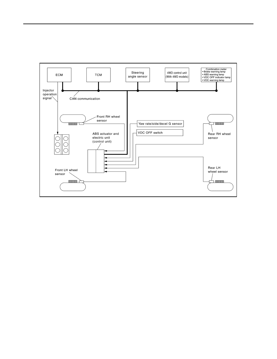
System Diagram
INFOID:0000000009718219
System Description
INFOID:0000000009718220
• In addition to the TCS/ABS function, the driver steering amount and brake operation amount are detected by
the steering angle sensor and pressure sensor, and the vehicle
′
s driving status (amount of under steering/
over steering) is determined by the information from the yaw rate/side/decel G sensor, wheel sensor, etc.,
and this information is used to improve vehicle stability by controlling the braking and engine power to all
four wheels.
• During VDC operation, it informs driver of system operation by blinking the VDC warning lamp.
• Electrical system diagnosis by CONSULT is available.
Component Parts Location
INFOID:0000000009718221
FOR USA
JSFIA1149GB