содержание .. 161 162 163 164 ..
Nissan Murano. Manual - part 163
AV-430
< DTC/CIRCUIT DIAGNOSIS >
[BOSE AUDIO WITH NAVIGATION]
STEERING SWITCH SIGNAL A CIRCUIT
STEERING SWITCH SIGNAL A CIRCUIT
Description
INFOID:0000000009721960
Transmits the steering switch signal to AV control unit.
Diagnosis Procedure
INFOID:0000000009721961
1.
CHECK STEERING SWITCH SIGNAL A CIRCUIT
1.
Turn ignition switch OFF.
2.
Disconnect AV control unit connector and spiral cable connector.
3.
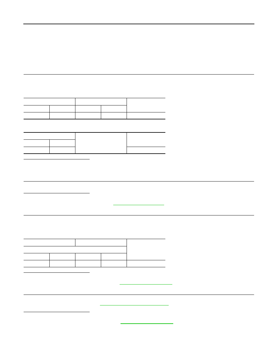
Check continuity between AV control unit harness connector and spiral cable harness connector.
4.
Check continuity between AV control unit harness connector and ground.
Is the inspection result normal?
YES
>> GO TO 2.
NO
>> Repair harness or connector.
2.
CHECK SPIRAL CABLE
Check spiral cable.
Is the inspection result normal?
YES
>> GO TO 3.
NO
>> Replace spiral cable. Refer to
3.
CHECK AV CONTROL UNIT VOLTAGE
1.
Connect AV control unit connector and spiral cable connector.
2.
Turn ignition switch ON.
3.
Check voltage between AV control unit harness connector.
Is the inspection result normal?
YES
>> GO TO 4.
NO
>> Replace AV control unit. Refer to
4.
CHECK STEERING SWITCH
1.
Turn ignition switch OFF.
2.
Check steering switch. Refer to
AV-430, "Component Inspection"
Is the inspection result normal?
YES
>> INSPECTION END
NO
>> Replace steering switch. Refer to
Component Inspection
INFOID:0000000009721962
Measure the resistance between the steering switch connector terminals 14 to 17 and 15 to 17.
AV control unit
Spiral cable
Continuity
Connector
Terminal
Connector
Terminal
M178
6
M33
24
Existed
AV control unit
Ground
Continuity
Connector
Terminal
M178
6
Not existed
(+)
(
−
)
Voltage
(Approx.)
AV control unit
Connector
Terminal
Connector
Terminal
M178
6
M178
15
5.0 V