Nissan Murano. Manual - part 143


  Главная      Nissan     Nissan Murano (2014 year) - Service Manual


поиск по сайту            


содержание   ..  141  142  143  144   ..


Nissan Murano. Manual - part 143


AV-350

< ECU DIAGNOSIS INFORMATION >

[BOSE AUDIO WITH NAVIGATION]

CAMERA CONTROL UNIT

Fail-Safe

INFOID:0000000009721857
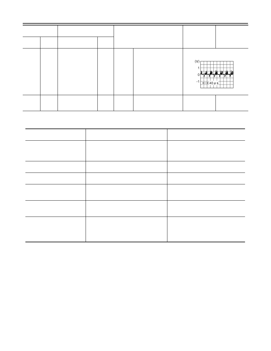
53

(B)

54

Rear camera image 
signal (+)

Input

Ignition 

switch 

ON

Input the waveform synchronized 

with the camera image signal.

54

Ground

Rear camera image 
signal (

)

Ignition 

switch 

ON

0  -  0.1  V

0  V

Terminal

(Wire color)

Description

Condition

Standard value

Reference value

(Approx.)

+

Signal name

Input/

Output

JSNIA0834GB

DTC

Display contents of CONSULT

Malfunction detection condition

Fail-safe condition

C1A03
VHCL SPEED SE CIRC

If the vehicle speed signal (wheel speed) from 
ABS actuator and electric unit (control unit) re-
ceived by the camera control unit via CAN com-
munication, are inconsistent

• LDW system is cancel
• BSW system is cancel

C1A04
ABS/TCS/VDC CIRC

If a malfunction occurs in the VDC/TCS/ABS 
system

• LDW system is cancel
• BSW system is cancel

C1A39
STRG SEN CIR

If the steering angle sensor is malfunction

• LDW system is cancel
• BSW system is cancel

U0122
VDC P-RUN DIAGNOSIS

If camera control unit detects an error signal 
that is received from ABS actuator and electric 
unit (control unit) via CAN communication

• LDW system is cancel
• BSW system is cancel

U0416
VDC CHECKSUM DIAGNOSIS

If camera control unit detects an error signal 
that is received from ABS actuator and electric 
unit (control unit) via CAN communication

• LDW system is cancel
• BSW system is cancel

U0428
ST ANGLE SENSOR CALIBRA-
TION

Neutral position adjustment of steering angle 
sensor is not complete.

• Predicted course line is not displayed.
• MOD (Moving Object Detection) function is 

stopped.

• LDW system is stopped.
• BSW system is stopped.

AV

CAMERA CONTROL UNIT

AV-351

< ECU DIAGNOSIS INFORMATION >

[BOSE AUDIO WITH NAVIGATION]

C

D

E

F

G

H

I

J

K

L

M

B

A

O

P

U1000
CAN COMM CIRCUIT

When camera control unit cannot transmit/re-
ceive CAN communication signal continuously 
for 2 seconds or more.

The following functions are stopped
• When communication of steering angle 

sensor signal is not normal

- Predicted course line is not displayed.
- MOD (Moving Object Detection) function is 

stopped.

- LDW system is stopped.
- BSW system is stopped.
- Front tire angle display is stopped.
- Using “SETTING” menu display, switch 

each indicator of predicted course line dis-
play and MOD switch to “OFF” (turn OFF) 
so that switch operation cannot be per-
formed.

• When communication of vehicle signal, 

wheel speed sensor signal, and shift signal 
is not normal

- Predicted course line is not displayed.
- MOD (Moving Object Detection) function is 

stopped.

- LDW system is stopped.
- BSW system is stopped.
- Using “SETTING” menu display, switch 

each indicator of predicted course line dis-
play and MOD switch to “OFF” (turn OFF) 
so that switch operation cannot be per-
formed

• When communication of sonar signal is not 

normal

- Predicted course line is not displayed.

U1010
CONTROL UNIT (CAN)

CAN initial diagnosis malfunction is detected.

• MOD (Moving Object Detection) function is 

stopped.

• LDW system is stopped.
• BSW system is stopped.

U111A
REAR CAMERA IMAGE SIGNAL

No-signal status of rear camera image signal is 
continued for 500 ms or more while ignition 
switch is ON.
NOTE:
Current malfunction is displayed only and is not 
saved.

• Camera image is not displayed (Gray 

screen display).

• LDW system is stopped.
• BSW system is stopped.

U1232
ST ANGLE SEN CALIB

Neutral position adjustment of steering angle 
sensor is performed. NG signal from steering 
angle sensor is received.

• Predicted course line is not displayed.
• MOD (Moving Object Detection) function is 

stopped.

• LDW system is stopped.
• BSW system is stopped.
• Tire icon is stopped.
• Using “SETTING” menu display, switch 

each indicator of predicted course line dis-
play and MOD switch to “OFF” (turn OFF) 
so that switch operation cannot be per-
formed.

U1305
CONFIG UNFINISH

The vehicle setting of camera control unit is in-
complete.
NOTE:
Current malfunction is displayed only and is not 
saved.

Operation is according to the vehicle setting 
value as default value.

U1308
R-CAMERA (R&L) CALIB JDG-
MNT

Camera image calibration is incomplete

• MOD (Moving Object Detection) function is 

stopped.

• LDW system is stopped.
• BSW system is stopped.

DTC

Display contents of CONSULT

Malfunction detection condition

Fail-safe condition

AV-352

< ECU DIAGNOSIS INFORMATION >

[BOSE AUDIO WITH NAVIGATION]

CAMERA CONTROL UNIT

DTC Inspection Priority Chart

INFOID:0000000009721858

If multiple DTCs are detected simultaneously, check them one by one depending on the following DTC inspec-
tion priority chart.

DTC Index

INFOID:0000000009721859

U1309
PUMP INPUT CURRENT JUDGE

Camera control unit detects the value of current 
from pump control unit is incorrect

• MOD (Moving Object Detection) function is 

stopped.

• LDW system is stopped.
• BSW system is stopped.

U130B
RR CAMERA COMM ERROR

Camera control unit receives the incorrect com-
munication signal from rear view camera

• MOD (Moving Object Detection) function is 

stopped.

• LDW system is stopped.
• BSW system is stopped.

U1310 PUMP ECU JUDGE

If the pump control unit is malfunction

• LDW system is stopped.
• BSW system is stopped.

Other

When camera control unit is not normal.

Switch to camera screen is not allowed.

When communication between camera control 
unit and each camera is not normal.

On applicable camera screen 

 marking 

(Red) is displayed.

When communication line between camera 
control unit and each camera image line are af-
fected by electromagnetic noises.

On applicable camera image screen, 

 dis-

play (Blue) is displayed.

DTC

Display contents of CONSULT

Malfunction detection condition

Fail-safe condition

Priority

Detected items (DTC)

1

• U1000: CAN COMM CIRCUIT
• U1010: CONTROL UNIT (CAN)

2

• U1232: ST ANGLE SEN CALIB
• U1305: CONFIG UNFINISH

3

• U0428: ST ANGLE SENSOR CALIBRATION

4

• U130B: RR CAMERA COMM ERROR 

5

• U1308: R-CAMERA (R&L) CALIB JDGMNT

6

• C1A04: ABS/TCS/VDC CIRC
• C1A39: STRG SEN CIR
• U0122: VDC P-RUN DIAGNOSIS
• U0416: VDC CHECKSUM DIAGNOSIS
• U111A: REAR CAMERA IMAGE SIGNAL
• U1309: PUMP INPUT CURRENT JUDGE
• U1310: PUMP ECU JUDGE

7

• C1A03: VHCL SPEED SE CIRC

DTC

CONSULT display

Warning lamp

“MOD” (Mov-

ing Object De-

tection) icon

Reference

Lane depar-

ture warning 

lamp

BSW warning 

lamp

C1A03

VHCL SPEED SE CIRC

ON

ON

Orange

DAS-58, "DTC Logic"

C1A04

ABS/TCS/VDC CIRC

ON

ON

Orange

DAS-59, "DTC Logic"

C1A39

STRG SEN CIR

ON

ON

Orange

DAS-60, "DTC Logic"

U0122

VDC P-RUN DIAGNOSIS

ON

ON

Orange

DAS-61, "DTC Logic"

U0416

VDC CHECKSUM DIAGNOSIS

ON

ON

Orange

DAS-62, "DTC Logic"

U0428

ST ANGLE SENSOR CALIBRATION

ON

ON

Orange

AV-378, "DTC Logic"

AV

CAMERA CONTROL UNIT

AV-353

< ECU DIAGNOSIS INFORMATION >

[BOSE AUDIO WITH NAVIGATION]

C

D

E

F

G

H

I

J

K

L

M

B

A

O

P

U1000

CAN COMM CIRCUIT

ON

ON

Orange

AV-379, "CAMERA 

CONTROL UNIT : 

DTC Logic"

U1010

CONTROL UNIT (CAN)

ON

ON

Orange

AV-381, "CAMERA 

CONTROL UNIT : 

DTC Logic"

U111A

REAR CAMERA IMAGE SIGNAL

ON

ON

Orange

AV-382, "DTC Logic"

U1232

ST ANGLE SEN CALIB

ON

ON

Orange

AV-406, "CAMERA 

CONTROL UNIT : 

DTC Logic"

U1305

CONFIG UNFINISH

ON

ON

Orange

AV-415, "DTC Logic"

U1308

R-CAMERA (R&L) CALIB JDGMNT

ON

ON

Orange

DAS-70, "DTC Logic"

U1309

PUMP INPUT CURRENT JUDGE

ON

ON

Blue

DAS-71, "DTC Logic"

U130B

RR CAMERA COMM ERROR

ON

ON

Orange

AV-417, "DTC Logic"

U1310

PUMP ECU JUDGE

ON

ON

Blue

DAS-73, "DTC Logic"

DTC

CONSULT display

Warning lamp

“MOD” (Mov-

ing Object De-

tection) icon

Reference

Lane depar-

ture warning 

lamp

BSW warning 

lamp


содержание   ..  141  142  143  144   ..