содержание .. 1425 1426 1427 1428 ..
Nissan Murano. Manual - part 1427
VTL-64
< REMOVAL AND INSTALLATION >
[WITHOUT 7 INCH DISPLAY]
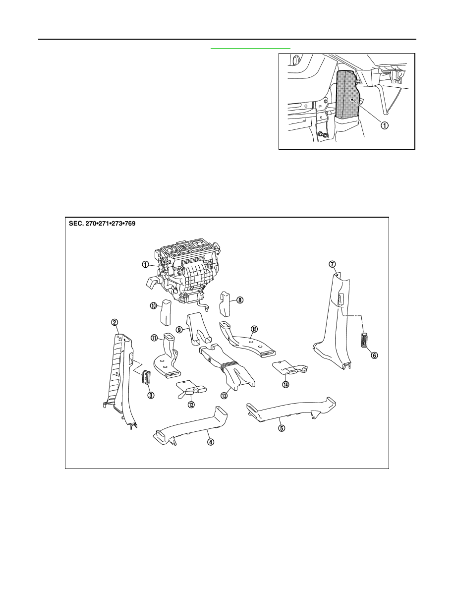
DUCT AND GRILLE
1.
Remove instrument lower cover RH. Refer to
2.
Remove rear foot duct 1 RH (1).
INSTALLATION
Install in the reverse order of removal.
REAR FOOT DUCT 2
REAR FOOT DUCT 2 : Exploded View
INFOID:0000000009721132
JPIIA0596ZZ
1.
Heater & cooling unit assembly
2.
Rear ventilator duct 4
(Center pillar lower garnish LH)
3.
Rear ventilator grille LH
4.
Rear ventilator duct 3 LH
5.
Rear ventilator duct 3 RH
6.
Rear ventilator grille RH
7.
Rear ventilator duct 4
(Center pillar lower garnish RH)
8.
Rear foot duct 1 RH
9.
Rear ventilator duct 1
10.
Rear foot duct 1 LH
11.
Rear foot duct 2 LH
12.
Rear foot duct 3 LH
13.
Rear ventilator duct 2
14.
Rear foot duct 3 RH
15.
Rear foot duct 2 RH
JPIIA0457ZZ