содержание .. 1403 1404 1405 1406 ..
Nissan Murano. Manual - part 1405
TM-162
< PERIODIC MAINTENANCE >
[CVT: RE0F09B]
ROAD TEST
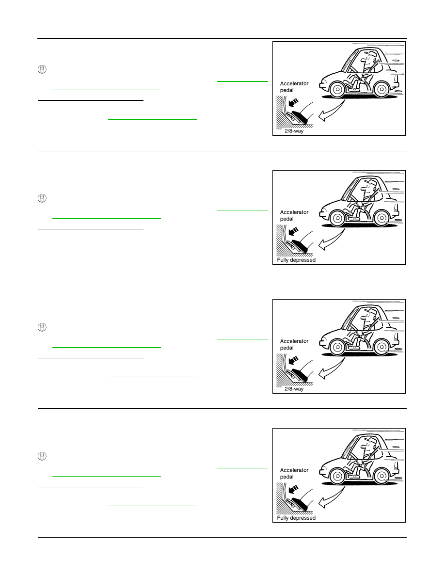
6.
Accelerate vehicle at 2/8 throttle opening and check “Vehicle
Speed When Shifting Gears”.
With CONSULT
-
Read vehicle speed and engine speed. Refer to
cle Speed When Shifting Gears"
Is the inspection result normal?
YES
>> GO TO 2.
NO
>> Refer to
. GO TO 2.
2.
CHECK VEHICLE SPEED WHEN SHIFTING GEARS (PART 2)
1.
Park vehicle on flat surface.
2.
Move selector lever to “D” position.
3.
Accelerate vehicle at 8/8 throttle opening and check “Vehicle
Speed When Shifting Gears”.
With CONSULT
-
Read vehicle speed and engine speed. Refer to
cle Speed When Shifting Gears"
Is the inspection result normal?
YES
>> GO TO 3.
NO
>> Refer to
. GO TO 3.
3.
CHECK OVERDRIVE OFF CONDITION (PART 1)
1.
Park vehicle on flat surface.
2.
Push overdrive control switch.
3.
Accelerate vehicle at 2/8 throttle opening and check “Vehicle
Speed When Shifting Gears”.
With CONSULT
-
Read vehicle speed and engine speed. Refer to
cle Speed When Shifting Gears"
Is the inspection result normal?
YES
>> GO TO 4.
NO
>> Refer to
. GO TO 4.
4.
CHECK OVERDRIVE OFF CONDITION (PART 2)
1.
Park vehicle on flat surface.
2.
Push overdrive control switch.
3.
Accelerate vehicle at 8/8 throttle opening and check “Vehicle
Speed When Shifting Gears”.
With CONSULT
-
Read vehicle speed and engine speed. Refer to
cle Speed When Shifting Gears"
Is the inspection result normal?
YES
>> GO TO 5.
NO
>> Refer to
. GO TO 5.
5.
CHECK “L” POSITION FUNCTION (PART 1)
1.
Park vehicle on flat surface.
2.
Move selector lever to “L” position.
SCIA6644E
SCIA4366E
SCIA6644E
SCIA4366E