Nissan Murano. Manual - part 1400


  Главная      Nissan     Nissan Murano (2014 year) - Service Manual


поиск по сайту            


содержание   ..  1398  1399  1400  1401   ..


Nissan Murano. Manual - part 1400


TM-142

< PRECAUTION >

[CVT: RE0F09B]

PRECAUTIONS

FOR USA AND CANADA : Precautions for Removing of Battery Terminal

INFOID:0000000010056674

•  When removing the 12V battery terminal, turn OFF the ignition

switch and wait at least 30 seconds.
NOTE:
ECU may be active for several tens of seconds after the ignition
switch is turned OFF. If the battery terminal is removed before ECU
stops, then a DTC detection error or ECU data corruption may
occur.

•  For vehicles with the 2-batteries, be sure to connect the main bat-

tery and the sub battery before turning ON the ignition switch.
NOTE:
If the ignition switch is turned ON with any one of the terminals of
main battery and sub battery disconnected, then DTC may be
detected.

•  After installing the 12V battery, always check "Self Diagnosis Result" of all ECUs and erase DTC.

NOTE:
The removal of 12V battery may cause a DTC detection error.

FOR USA AND CANADA : Precaution for On Board Diagnosis (OBD) System of CVT 
and Engine

INFOID:0000000009719546

The ECM has an on board diagnostic system. It will light up the malfunction indicator (MIL) to warn the driver
of a malfunction causing emission deterioration.

CAUTION:

• Be sure to turn the ignition switch OFF and disconnect the battery cable from the negative terminal

before any repair or inspection work. The open/short circuit of related switches, sensors, solenoid
valves, etc. will cause the MIL to light up.

• Be sure to connect and lock the connectors securely after work. A loose (unlocked) connector will

cause the MIL to light up due to an open circuit. (Be sure the connector is free from water, grease,
dirt, bent terminals, etc.)

• Be sure to route and secure the harnesses properly after work. Interference of the harness with a

bracket, etc. may cause the MIL to light up due to a short circuit.

• Be sure to connect rubber tubes properly after work. A misconnected or disconnected rubber tube

may cause the MIL to light up due to a malfunction of the EVAP system or fuel injection system, etc.

• Be sure to erase the unnecessary malfunction information (repairs completed) from the TCM and

ECM before returning the vehicle to the customer.

FOR USA AND CANADA : Precaution for TCM and Transaxle Assembly Replacement

INFOID:0000000009719547

CAUTION:

• To replace TCM, refer to 

TM-8, "Description"

.

• To replace transaxle assembly, refer to 

TM-10, "Description"

.

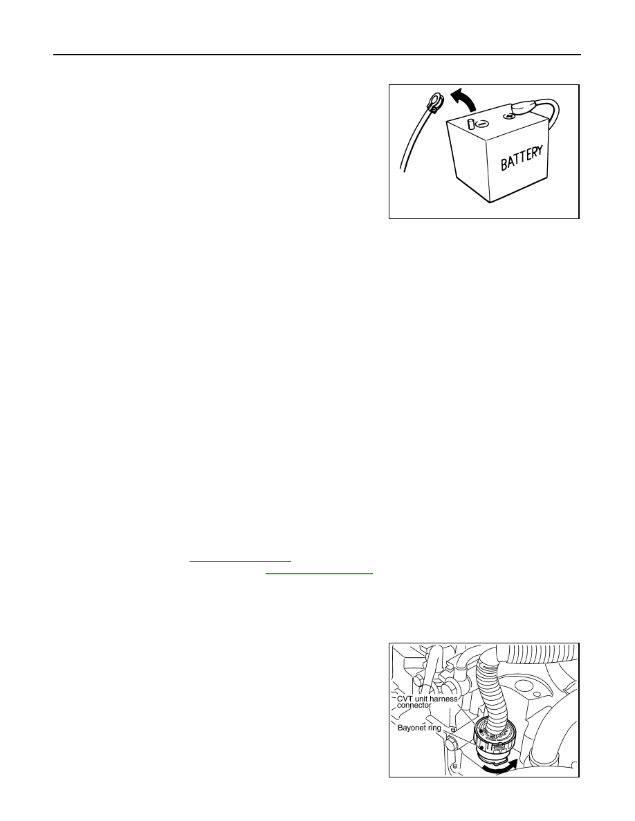
FOR USA AND CANADA : Removal and Installation Procedure for CVT Unit Connec-
tor

INFOID:0000000009719548

REMOVAL

Rotate bayonet ring counterclockwise. Pull out CVT unit harness
connector upward and remove it.

SEF289H

SCIA2096E

PRECAUTIONS

TM-143

< PRECAUTION >

[CVT: RE0F09B]

C

E

F

G

H

I

J

K

L

M

A

B

TM

N

O

P

INSTALLATION

1.

Align 

 marking on CVT unit harness connector terminal body

with 

†

 marking on bayonet ring. Insert CVT unit harness con-

nector. Then rotate bayonet ring clockwise.

2.

Rotate bayonet ring clockwise until 

 marking on CVT unit har-

ness connector terminal body is aligned with the slit on bayonet
ring as shown in the figure (correctly fitting condition). Install
CVT unit harness connector to CVT unit harness connector ter-
minal body.

CAUTION:

• Securely align 

 marking on CVT unit harness connector

terminal body with bayonet ring slit. Then, be careful not
to make a half fit condition as shown in the figure.

• Never mistake the slit of bayonet ring for other dent por-

tion.

FOR USA AND CANADA : Precaution

INFOID:0000000009719549

• Turn ignition switch OFF and disconnect negative battery

cable before connecting or disconnecting the TCM harness
connector. Because battery voltage is applied to TCM even if
ignition switch is turned OFF.

SCIA2097E

SCIA2098E

SCIA2099E

SEF289H

TM-144

< PRECAUTION >

[CVT: RE0F09B]

PRECAUTIONS

• When connecting or disconnecting pin connectors into or

from TCM, do not damage pin terminals (bend or break).
Check that there are not any bends or breaks on TCM pin ter-
minal, when connecting pin connectors.

• Perform TCM input/output signal inspection and check

whether TCM functions normally or not before replacing TCM.

TM-116, "Reference Value"

.

• Perform “DTC Confirmation Procedure” after performing each

TROUBLE DIAGNOSIS.
If the repair is completed the DTC should not be displayed in
the “DTC Confirmation Procedure”.

• Always use the specified brand of CVT fluid. Refer to 

MA-15, "FOR

NORTH AMERICA : Fluids and Lubricants"

.

• Use lint-free paper, not cloth rags, during work.
• Dispose of the waste oil using the methods prescribed by law, ordi-

nance, etc. after replacing the CVT fluid.

FOR USA AND CANADA : Service Notice or Precaution

INFOID:0000000009719550

OBD-II SELF-DIAGNOSIS

• CVT self-diagnosis is performed by the TCM in combination with the ECM. The results can be read through

the blinking pattern of the Malfunction Indicator Lamp (MIL). Refer to the table on 

TM-38, "CONSULT Func-

tion"

 for the indicator used to display each self diagnostic result.

• The self diagnostic results indicated by the MIL are automatically stored in both the ECM and TCM memo-

ries.
Always perform the procedure on 

TM-36, "Diagnosis Description"

 to complete the repair and avoid

unnecessary blinking of the MIL.

For details of OBD-II, refer to 

EC-118, "Diagnosis Description"

.

• Certain systems and components, especially those related to OBD, may use the new style slide-lock-

ing type harness connector. For description and how to disconnect, refer to 

PG-86

.

FOR USA AND CANADA : ATFTEMP COUNT Conversion Table 

INFOID:0000000009719551

SEF291H

MEF040DA

JSBIA1315ZZ

ATFTEMP COUNT

Temperature 

°

C (

°

F)

ATFTEMP COUNT

Temperature 

°

C (

°

F)

4

–30 (–22)

177

90 (194)

8

–20 (–4)

183

95 (203)

13

–10 (14)

190

100 (212)

17

–5 (23)

196

105 (221)

PRECAUTIONS

TM-145

< PRECAUTION >

[CVT: RE0F09B]

C

E

F

G

H

I

J

K

L

M

A

B

TM

N

O

P

FOR MEXICO

FOR MEXICO : Precaution for Supplemental Restraint System (SRS) "AIR BAG" and 
"SEAT BELT PRE-TENSIONER"

INFOID:0000000009719552

The Supplemental Restraint System such as “AIR BAG” and “SEAT BELT PRE-TENSIONER”, used along
with a front seat belt, helps to reduce the risk or severity of injury to the driver and front passenger for certain
types of collision. Information necessary to service the system safely is included in the “SRS AIR BAG” and
“SEAT BELT” of this Service Manual.

WARNING:

Always observe the following items for preventing accidental activation.
• To avoid rendering the SRS inoperative, which could increase the risk of personal injury or death in

the event of a collision that would result in air bag inflation, all maintenance must be performed by
an authorized NISSAN/INFINITI dealer.

• Improper maintenance, including incorrect removal and installation of the SRS, can lead to personal

injury caused by unintentional activation of the system. For removal of Spiral Cable and Air Bag
Module, see “SRS AIR BAG”.

• Never use electrical test equipment on any circuit related to the SRS unless instructed to in this Ser-

vice Manual. SRS wiring harnesses can be identified by yellow and/or orange harnesses or harness
connectors.

PRECAUTIONS WHEN USING POWER TOOLS (AIR OR ELECTRIC) AND HAMMERS

WARNING:

Always observe the following items for preventing accidental activation.
• When working near the Air Bag Diagnosis Sensor Unit or other Air Bag System sensors with the

ignition ON or engine running, never use air or electric power tools or strike near the sensor(s) with
a hammer. Heavy vibration could activate the sensor(s) and deploy the air bag(s), possibly causing
serious injury.

• When using air or electric power tools or hammers, always switch the ignition OFF, disconnect the

battery, and wait at least 3 minutes before performing any service.

21

0 (32)

201

110 (230)

27

5 (41)

206

115 (239)

32

10 (50)

210

120 (248)

39

15 (59)

214

125 (257)

47

20 (68)

218

130 (266)

55

25 (77)

221

135 (275)

64

30 (86)

224

140 (284)

73

35 (95)

227

145 (293)

83

40 (104)

229

150 (302)

93

45 (113)

231

155 (311)

104

50 (122)

233

160 (320)

114

55 (131)

235

165 (329)

124

60 (140)

236

170 (338)

134

65 (149)

238

175 (347)

143

70 (158)

239

180 (356)

152

75 (167)

241

190 (374)

161

80 (176)

243

200 (392)

169

85 (185)

ATFTEMP COUNT

Temperature 

°

C (

°

F)

ATFTEMP COUNT

Temperature 

°

C (

°

F)


содержание   ..  1398  1399  1400  1401   ..