содержание .. 1376 1377 1378 1379 ..
Nissan Murano. Manual - part 1378
TM-54
< DTC/CIRCUIT DIAGNOSIS >
[CVT: RE0F09B]
P0710 TRANSMISSION FLUID TEMPERATURE SENSOR A
8.
Stop the vehicle.
9.
Check the first trip DTC.
With GST
1.
Turn ignition switch OFF and cool the engine.
2.
Start the engine and wait for at least 2 minutes.
3.
Drive the vehicle and maintain the following conditions for 17 minutes or more.
4.
Stop the vehicle.
5.
Check the first trip DTC.
Is “P0710” detected?
YES
>> Go to
NO
>> GO TO 3.
3.
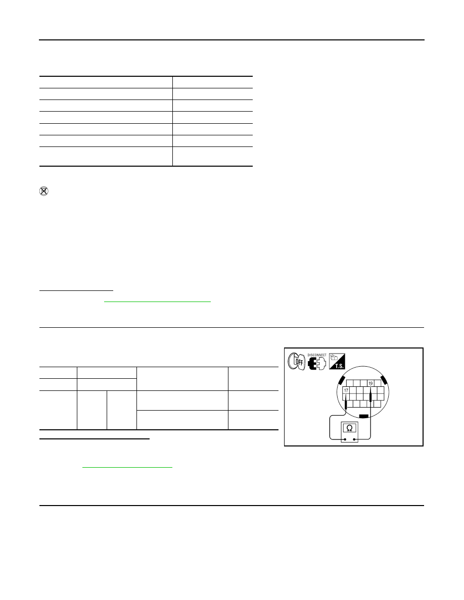
CHECK CVT FLUID TEMPERATURE SENSOR
1.
Turn ignition switch OFF.
2.
Disconnect CVT unit connector.
3.
Check resistance between CVT unit connector terminals.
Is the inspection result normal?
YES
>> INSPECTION END
NO
>> Replace the transaxle assembly due to malfunction in the CVT fluid temperature sensor. Refer to
Diagnosis Procedure
INFOID:0000000009719442
1.
CHECK CVT FLUID TEMPERATURE SENSOR CIRCUIT
1.
Turn ignition switch OFF.
2.
Disconnect TCM connector.
3.
Check resistance between TCM vehicle side harness connector terminals.
Accelerator pedal position
: 1.0/8 or more
Vehicle speed
: 10 km/h (7 MPH) or more
CVT fluid temperature before engine start
Driving time
−
40
°
C (
−
40
°
F) –
−
31
°
C (
−
23.8
°
F)
17 minutes or more
−
30
°
C (
−
22
°
F) –
−
21
°
C (
−
5.8
°
F)
15 minutes or more
−
20
°
C (
−
4
°
F) –
−
11
°
C (
−
12.2
°
F)
12 minutes or more
−
10
°
C (14
°
F) –
−
1
°
C (30.2
°
F)
9 minutes or more
0
°
C (32
°
F) – 9
°
C (48.2
°
F)
6 minutes or more
10
°
C (50
°
F) or more
—
(Go to 4.)
Selector lever
: “D” position
Accelerator pedal position
: 1.0/8 or more
Vehicle speed
: 10 km/h (7 MPH) or more
CVT unit
CVT unit
Condition
Resistance
(Approx.)
Connector
Terminal
F24
17
19
When CVT fluid temperature
is 20
°
C (68
°
F)
6.5 k
Ω
When CVT fluid temperature
is 80
°
C (176
°
F)
0.9 k
Ω
AWDIA0098ZZ