Nissan Murano. Manual - part 1351


  Главная      Nissan     Nissan Murano (2014 year) - Service Manual


поиск по сайту            


содержание   ..  1349  1350  1351  1352   ..


Nissan Murano. Manual - part 1351


ST-98

< REMOVAL AND INSTALLATION >

[WITHOUT HEATED STEERING WHEEL]

STEERING GEAR AND LINKAGE

e.

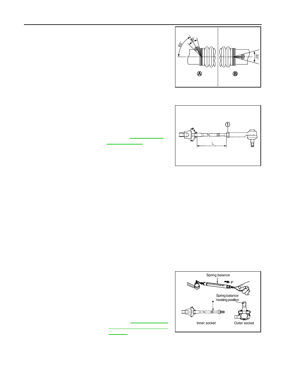
Bent cut end of the wire toward rack axial as shown in the figure
after twisting the wire 4 to 4.5 turns so that cut end does not con-
tact with boot.

19. Install cylinder tubes to gear housing assembly.

20. Install low pressure piping.

21. Adjust inner socket to standard length (L), and then tighten lock

nut (1) to the specified torque. Check length again after tighten-
ing lock nut.

CAUTION:

Adjust toe-in after this procedure. The length achieved after
toe-in adjustment is not necessary the above value.

Inspection

INFOID:0000000009721534

INSPECTION AFTER DISASSEMBLY

Boot

Check boot for cracks, and replace it if a malfunction is detected.

Rack Assembly

Check rack for damage or wear, and replace it if a malfunction is detected.

Gear-Sub Assembly

• Check gear-sub assembly for damage or wear, and replace it if a malfunction is detected.
• Rotate gear-sub assembly and check for torque variation or rattle, and replace it if a malfunction is detected.

Gear Housing Assembly

Check gear housing assembly for damage and scratches (inner wall). Replace if there are.

Outer Socket and Inner Socket

Check the following items and replace the component if it does not meet the standard.

BALL JOINT SWINGING TORQUE

Hook a spring balance at the point shown in the figure and pull the
spring balance. Make sure that the spring balance reads the speci-
fied value when ball stud and inner socket start to move. Replace
outer socket and inner socket if they are outside the standard.

A

: Gear housing RHD side

B

: Gear housing LHD side

JSGIA0325ZZ

Standard

Inner socket length (L)

: Refer to 

ST-109, "Inner 

Socket Length"

.

JPGIA0187ZZ

Standard

(Measuring point of outer socket: Stud cotter pin 
mounting hole)

Outer socket

: Refer to 

ST-109, "Socket 

Swing Force and Rotating 
Torque"

.

SGIA0896E

STEERING GEAR AND LINKAGE

ST-99

< REMOVAL AND INSTALLATION >

[WITHOUT HEATED STEERING WHEEL]

C

D

E

F

H

I

J

K

L

M

A

B

ST

N

O

P

BALL JOINT ROTATING TORQUE

Make sure that the reading is within the following specified range
using preload gauge (A) [SST: ST3127S000 (J-25765-A)]. Replace
outer socket if the reading is outside the specified value.

BALL JOINT AXIAL END PLAY

Apply an axial load of 490 N (50 kg, 110 lb) to ball stud. Using a dial
gauge, measure amount of stud movement, and then make sure that
the value is within the following specified range. Replace outer
socket (1) and inner socket (2) if the measured value is outside the
standard.

INSPECTION AFTER INSTALLATION

• Check if steering wheel turns smoothly when it is turned several times fully to the end of the left and right.
• Check the steering wheel play, neutral position steering wheel, steering wheel turning force, and front wheel

turning angle. Refer to 

ST-80, "Inspection"

.

• Check the fluid level, fluid leakage, and air bleeding hydraulic system. Refer to 

ST-78, "Inspection"

.

Standard 

(Measuring point of inner socket: “*” mark shown in 
the figure)

Inner socket

: Refer to 

ST-109, "Socket 

Swing Force and Rotating 
Torque"

.

Standard

Rotating torque

: Refer to 

ST-109, "Socket 

Swing Force and Rotating 
Torque"

.

SGIA1382E

Standard

Outer socket

Refer to 

ST-109, "Socket Axial 

End Play"

.

Inner socket

: Refer to 

ST-109, "Socket Axial 

End Play"

.

JSGIA0109ZZ

ST-100

< REMOVAL AND INSTALLATION >

[WITHOUT HEATED STEERING WHEEL]

POWER STEERING OIL PUMP

POWER STEERING OIL PUMP

Exploded View

INFOID:0000000009721535

REMOVAL

DISASSEMBLY

1.

Power steering oil pump

: Vehicle front

Refer to 

GI-4, "Components"

 for symbols in the figure.

JSGIA0326GB

1.

Pulley

2.

Oil seal

3.

Front bracket

4.

Suction pipe

5.

O-ring 

6.

Body assembly 

7.

Flow control valve spring

8.

Flow control valve 

9.

Flow control valve sub assembly

JSGIA0327GB

POWER STEERING OIL PUMP

ST-101

< REMOVAL AND INSTALLATION >

[WITHOUT HEATED STEERING WHEEL]

C

D

E

F

H

I

J

K

L

M

A

B

ST

N

O

P

Removal and Installation

INFOID:0000000009721536

REMOVAL

1.

Drain power steering fluid from reservoir tank.

2.

Remove front road wheel and tires.

3.

Remove splash guard. Refer to 

EXT-26, "FENDER PROTECTOR : Exploded View"

.

4.

Loosen drive belt. Refer to 

EM-17, "Removal and Installation"

.

5.

Remove drive belt from oil pump pulley.

6.

Remove copper washers and eye bolt (drain fluid from their pipings).

7.

Remove suction hose (drain fluid from their pipings).

8.

Remove oil pump mounting bolts, and then remove oil pump.

CAUTION:

Never damage drive shaft boot.

INSTALLATION

Note the following, and install in the reverse order of removal.
• When installing suction hoses (1), refer to the figure.

CAUTION:

• Never apply fluid to the hose (1) and tube (2).
• Insert hose securely until it contacts spool (A) of tube.
• Leave clearance (L) when installing clamp (3).

• When installing eye bolt (1) and copper washers (2) to oil pump

(3), refer to the figure.

CAUTION:

• Never reuse copper washer.
• Apply power steering fluid to around copper washer, then

install eye bolt.

• Install eye bolt with eye joint (assembled to high pressure

hose) (B) protrusion (A) facing with pump side cutout, and
then tighten it to the specified torque after tightening by
hand. Refer to 

ST-106, "Exploded View"

.

• Securely insert harness connector to pressure sensor.

• Adjust belt tension. Refer to 

EM-17, "Tension Adjustment"

.

• Check fluid level, fluid leakage and air bleeding hydraulic system after the installation. Refer to 

ST-78,

"Inspection"

.

Disassembly and Assembly

INFOID:0000000009721537

DISASSEMBLY

1.

Remove rear bracket.

10. O-ring

11.

O-ring

12. Front side plate

13. Vane

14. Rotor

15. Cam ring 

16. Dowel pin

17. Rear side plate

18. O-ring

19. Teflon ring

20. Rear cover

21. Rear bracket

A.

Oil seal lip

: Apply power steering fluid.

: Apply multi-purpose grease.

Refer to 

GI-4, "Components"

 for symbols not described on the above.

Standard

L

: 3 – 8 mm (0.12 – 0.31 in)

JSGIA0118ZZ

SGIA1379E


содержание   ..  1349  1350  1351  1352   ..