Nissan Murano. Manual - part 1342


  Главная      Nissan     Nissan Murano (2014 year) - Service Manual


поиск по сайту            


содержание   ..  1340  1341  1342  1343   ..


Nissan Murano. Manual - part 1342


ST-62

< REMOVAL AND INSTALLATION >

[WITH HEATED STEERING WHEEL]

POWER STEERING OIL PUMP

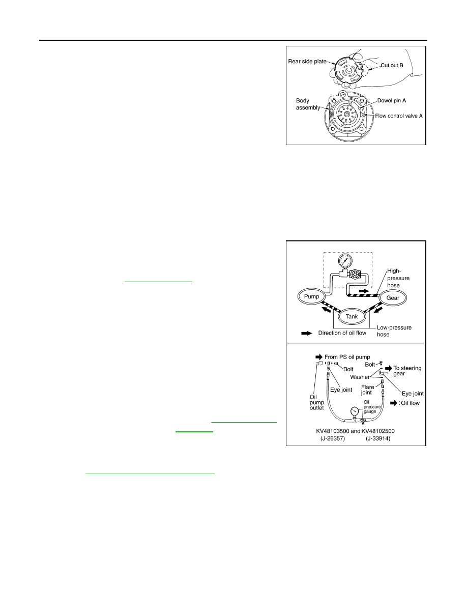
11. Install rear side plate with dowel pin A on flow control valve A

side as shown in the figure aligning with rear side plate cutout B
to cartridge.

12. Apply recommended fluid to O-ring, and then install O-ring to

body assembly.

13. Apply recommended fluid to O-ring, and then install O-ring to

rear side plate.

14. Apply recommended fluid to Teflon ring, and then install Teflon

ring to rear side plate.

15. Install rear cover to body assembly.

16. Apply recommended fluid to O-ring, and then install O-ring to

body assembly.

17. Install suction pipe to body assembly.

18. Install rear bracket.

Inspection

INFOID:0000000009721497

RELIEF OIL PRESSURE

CAUTION:

Make sure that belt tension is normal before starting the following procedure.
1.

Connect the oil pressure gauge [SST: KV48103500 (J-26357)]
and the oil pressure gauge adapter [SST: KV48102500 (J-
33914)] between oil pump discharge connector and high-pres-
sure hose. Bleed air from the hydraulic circuit while opening
valve fully. Refer to 

ST-33, "Inspection"

.

2.

Start the engine. Run the engine until oil temperature reaches
50 to 80

°

C (122 to 176

°

F).

CAUTION:

• Leave the valve of the oil pressure gauge fully open while

starting and running the engine. If engine is started with
the valve closed, the hydraulic pressure in oil pump goes
up to the relief pressure along with unusual increase of oil
temperature.

• Be sure to keep hose clear of belts and other parts when

engine is started.

3.

Fully close the oil pressure gauge valve with engine at idle and
measure the relief oil pressure.

CAUTION:

Never keep valve closed for 10 seconds or longer.

4.

Open the valve slowly after measuring. Repair oil pump if the relief oil pressure is outside the standard.
Refer to 

ST-59, "Disassembly and Assembly"

.

5.

Disconnect the oil pressure gauge from hydraulic circuit.

PGIA0035E

Standard

Relief oil pressure

: Refer to 

ST-68, "Relief Oil 

Pressure"

.

SGIA0915E

POWER STEERING OIL PUMP

ST-63

< REMOVAL AND INSTALLATION >

[WITH HEATED STEERING WHEEL]

C

D

E

F

H

I

J

K

L

M

A

B

ST

N

O

P

6.

When installing eye bolt (1) and copper washers (2) to oil pump
(3), refer to the figure.

CAUTION:

• Never reuse copper washer.
• Apply power steering fluid or equivalent to around copper

washer, then install eye bolt.

• Install eye bolt with eye joint (assembled to high pressure

hose) (B) protrusion (A) facing with pump side cutout, and
then tighten it to the specified torque after tightening by
hand. Refer to 

ST-64, "Exploded View"

.

• Securely insert harness connector to pressure sensor.

7.

Check fluid level, fluid leakage and air bleeding hydraulic sys-
tem after the installation. Refer to 

ST-33, "Inspection"

.

BEFORE DISASSEMBLY

Disassemble oil pump only when the following malfunctions occur.
• If oil leakage is found on oil pump.
• Oil pump pulley is damaged or deformed.
• Performance of oil pump is low. 

AFTER DISASSEMBLY

Body Assembly and Rear Cover Inspection

• Check body assembly and rear cover for internal damage. Replace rear cover if it is damaged. Replace oil

pump assembly if body assembly is damaged.

Cartridge Assembly Inspection

• Check cam ring, rotor and vane for damage. Replace cartridge assembly if necessary.

Side Plate Inspection

• Check side plate for damage. Replace side plate if necessary.

Flow Control Valve Inspection

• Check flow control valve and spring for damage. Replace if necessary.

SGIA1379E

ST-64

< REMOVAL AND INSTALLATION >

[WITH HEATED STEERING WHEEL]

HYDRAULIC LINE

HYDRAULIC LINE

Exploded View

INFOID:0000000009721498

Removal and Installation

INFOID:0000000009721499

CAUTION:

1.

Reservoir tank bracket

2.

Bushing

3.

Reservoir tank

4.

Suction hose

5.

Clamp

6.

Copper washer

7.

High pressure piping

8.

Steering gear assembly

9.

Low pressure hose

10. Eye bolt

A.

To power steering oil pump suction 
hose.

B.

To power steering oil pump.

: Vehicle front

: Apply power steering fluid.

Refer to 

GI-4, "Components"

 for symbols not described on the above.

JSGIA0608GB

HYDRAULIC LINE

ST-65

< REMOVAL AND INSTALLATION >

[WITH HEATED STEERING WHEEL]

C

D

E

F

H

I

J

K

L

M

A

B

ST

N

O

P

• Never apply fluid to the hose (1) and tube (2).
• Insert hose securely until it contacts spool (A) of tube.
• Leave clearance (L) when installing clamp (3).

• Install eye bolt with eye joint (assembled to high pressure

hose) (B) protrusion (A) facing with pump side cutout, and
then tighten it to the specified torque after tightening by hand.
Refer to 

ST-64, "Exploded View"

.

• Securely insert harness connector to pressure sensor.
• Apply power steering fluid to around copper washer, then

install eye bolt.

• Never reuse copper washer.

Standard

L

: 3 – 8 mm (0.12 – 0.31 in)

JSGIA0118ZZ

SGIA1379E


содержание   ..  1340  1341  1342  1343   ..