Nissan Murano. Manual - part 1338


  Главная      Nissan     Nissan Murano (2014 year) - Service Manual


поиск по сайту            


содержание   ..  1336  1337  1338  1339   ..


Nissan Murano. Manual - part 1338


ST-46

< REMOVAL AND INSTALLATION >

[WITH HEATED STEERING WHEEL]

STEERING GEAR AND LINKAGE

STEERING GEAR AND LINKAGE

Exploded View

INFOID:0000000009721490
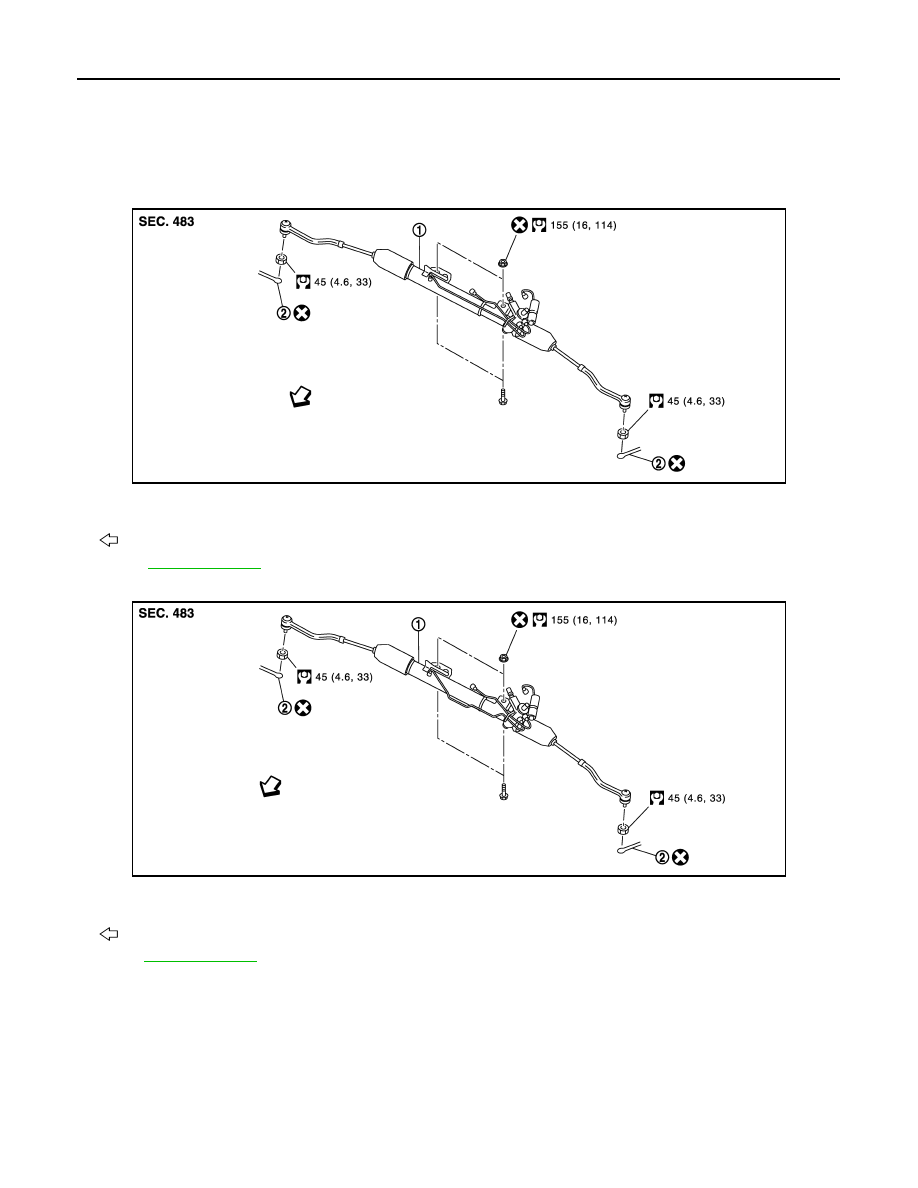
REMOVAL

2WD models

AWD models

DISASSEMBLY

JSGIA0606GB

1.

Steering gear assembly

2.

Cotter pin

: Vehicle front

Refer to 

GI-4, "Components"

 for symbols in the figure.

JSGIA0607GB

1.

Steering gear assembly

2.

Cotter pin

: Vehicle front

Refer to

GI-4, "Components"

 for symbols in the figure.

STEERING GEAR AND LINKAGE

ST-47

< REMOVAL AND INSTALLATION >

[WITH HEATED STEERING WHEEL]

C

D

E

F

H

I

J

K

L

M

A

B

ST

N

O

P

2WD models

JSGIA0571GB

1.

Low pressure piping

2.

Rear cover cap

3.

Gear-sub assembly

4.

Power steering solenoid valve

5.

O-ring

6.

Adjusting screw

7.

Spring

8.

Retainer

9.

Outer socket

10. Boot clamp

11.

Boot

12. Inner socket

13. Boot clamp (stainless wire)

14. Cylinder tube

15. Gear housing assembly

16. Rack oil seal

17. Rack assembly

18. Rack Teflon ring

19. O-ring

20. End cover assembly

: Apply power steering fluid.

: Apply Genuine Medium Strength Thread Locking Sealant or equivalent. Refer to 

GI-22, "Recommended Chemical Prod-

ucts and Sealants"

.

: Apply Genuine High Performance Thread Sealant or equivalent. Refer to 

GI-22, "Recommended Chemical Products and 

Sealants"

.

: Apply multi-purpose grease.

Refer to 

GI-4, "Components"

 for symbols not described on the above.

ST-48

< REMOVAL AND INSTALLATION >

[WITH HEATED STEERING WHEEL]

STEERING GEAR AND LINKAGE

AWD models

Removal and Installation

INFOID:0000000009721491

REMOVAL

1.

Set the vehicle to the straight-ahead position.

2.

Remove front road wheel and tires.

3.

Remove splash guards (RH and LH). Refer to 

EXT-26, "FENDER PROTECTOR : Exploded View"

.

4.

Remove engine under cover. Refer to 

EXT-29, "Exploded View"

.

5.

Remove exhaust front tube. Refer to 

EX-5, "Exploded View"

.

6.

Separate the rear propeller shaft (front side). Refer to 

DLN-85, "Exploded View"

 (AWD models). 

7.

Remove heat insulator from front floor. 

JSGIA0572GB

1.

Low pressure piping

2.

Rear cover cap

3.

Gear-sub assembly

4.

Power steering solenoid valve

5.

O-ring

6.

Adjusting screw

7.

Spring

8.

Retainer

9.

Outer socket

10. Boot clamp

11.

Boot

12. Inner socket

13. Boot clamp (stainless wire)

14. Cylinder tube

15. Gear housing assembly

16. Rack oil seal

17. Rack assembly

18. Rack Teflon ring

19. O-ring

20. End cover assembly

: Apply power steering fluid.

: Apply Genuine Medium Strength Thread Locking Sealant or equivalent. Refer to 

GI-22, "Recommended Chemical Prod-

ucts and Sealants"

.

: Apply Genuine High Performance Thread Sealant or equivalent. Refer to 

GI-22, "Recommended Chemical Products and 

Sealants"

.

: Apply multi-purpose grease.

Refer to 

GI-4, "Components"

 for symbols not described on the above.

STEERING GEAR AND LINKAGE

ST-49

< REMOVAL AND INSTALLATION >

[WITH HEATED STEERING WHEEL]

C

D

E

F

H

I

J

K

L

M

A

B

ST

N

O

P

8.

Remove cotter pin (1), and then loosen the nuts.

9.

Remove steering outer socket (2) from steering knuckle (3) so
as not to damage ball joint boot (4) using a ball joint remover
(commercial service tool).

CAUTION:

Temporarily tighten the nut to prevent damage to threads
and to prevent the ball joint remover from suddenly coming
off.

10. Remove high pressure piping and low pressure hose of hydrau-

lic piping, and then drain power steering fluid.

11. Remove steering hydraulic piping bracket from front steering

gear assembly.

12. Remove power steering solenoid valve harness connector (1)

and harness clip.

13. Remove lower joint fixing bolt (steering gear side).

14. Separate the lower shaft from the steering gear assembly by sliding the slide shaft.

CAUTION:

• Spiral cable may be cut if steering wheel turns while separating steering column assembly and

steering gear assembly. Be sure to secure steering wheel using string to avoid turning.

• When removing lower shaft, never insert a tool, such as a screwdriver, into the yoke groove to

pull out the lower shaft. In case of the violation of the above, replace lower shaft with a new one.

15. Remove the stabilizer assembly. Refer to 

FSU-14, "Exploded View"

.

16. Support front suspension member with a suitable jack.
17. Remove engine mounting insulator (rear) mounting bolt (lower side). Refer to 

EM-72, "2WD : Exploded

View"

 (2WD models), 

EM-81, "AWD : Exploded View"

 (AWD models).

18. Remove engine mounting insulator (LH). Refer to 

EM-72, "2WD : Exploded View"

 (2WD models), 

EM-81,

"AWD : Exploded View"

 (AWD models). 

19. Remove the mounting bolts and nuts of steering gear assembly.

20. Remove member stay, front suspension member fixing bolts and nuts. Refer to 

FSU-16, "Exploded View"

.

21. Lower the suitable jack for the front suspension member to the steering gear assembly can be removed.

INSTALLATION

Note the following, and install in the reverse order of removal.

CAUTION:

Spiral cable may be cut if steering wheel turns while separating steering column assembly and steer-
ing gear assembly. Be sure to secure steering wheel using string to avoid turning.

JSGIA0320ZZ

: Bolt

JSGIA0321ZZ

JSGIA0322ZZ


содержание   ..  1336  1337  1338  1339   ..