содержание .. 1334 1335 1336 1337 ..
Nissan Murano. Manual - part 1336
ST-38
< REMOVAL AND INSTALLATION >
[WITH HEATED STEERING WHEEL]
STEERING COLUMN
9.
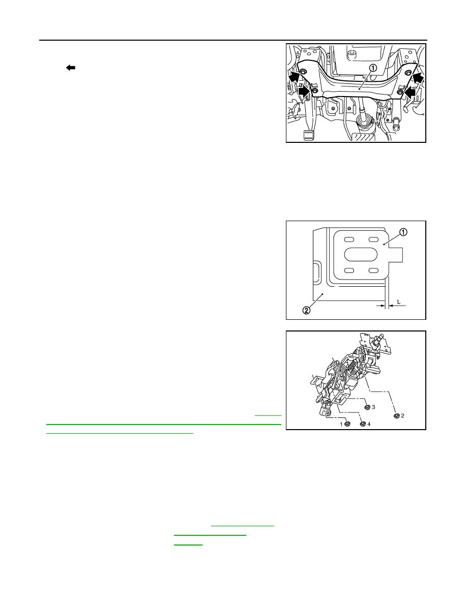
Remove knee protector (1).
10. Disconnect each switch harness connectors installed to steering
column assembly.
11. Remove the upper joint mounting bolt and nut (lower shaft side),
and separate the upper joint from lower shaft.
CAUTION:
When removing upper joint, never insert a tool, such as a
screwdriver, into the yoke groove to pull out the upper joint.
In case of the violation of the above, replace upper joint
with a new one.
12. Remove steering column assembly.
CAUTION:
• Never give axial impact to steering column assembly during removal.
• Never move steering gear assembly when removing steering column assembly.
INSTALLATION
Note the following, and install in the reverse order of removal.
• Install the slide plate (1) and steering column housing (2) so that
the mounting dimensions (L) is within the specified range as
described below.
• Tighten the mounting bolts in the order shown in the figure when
installing the steering column assembly.
• Be careful of the following points when installing the steering col-
umn assembly.
CAUTION:
• Never give axial impact to steering column assembly during
installation.
• Never move steering gear assembly.
• Never reuse the joint mounting nut (lower shaft side).
• Adjust neutral position of steering angle sensor. Refer to
"ADJUSTMENT OF STEERING ANGLE SENSOR NEUTRAL
POSITION : Special Repair Requirement"
.
WITHOUT ELECTRIC MOTOR : Inspection
INFOID:0000000009721483
INSPECTION AFTER REMOVAL
• Check each part of steering column assembly for damage or other malfunctions. Replace if necessary.
• Measure steering column assembly rotating torque using a preload gauge [SST: ST3127S000 (J-25765-A)].
Replace steering column assembly if outside the standard.
: Bolt
JSGIA0306ZZ
Standard
L
: 2.0 mm (0.079 in) or less
JSGIA0315ZZ
JSGIA0310ZZ
Standard
Rotating torque
: Refer to