Nissan Murano. Manual - part 1330


  Главная      Nissan     Nissan Murano (2014 year) - Service Manual


поиск по сайту            


содержание   ..  1328  1329  1330  1331   ..


Nissan Murano. Manual - part 1330


ST-14

< BASIC INSPECTION >

[WITH HEATED STEERING WHEEL]

STEERING WHEEL

STEERING WHEEL

Inspection

INFOID:0000000009721464

NEUTRAL POSITION STEERING WHEEL

1.

Check that steering gear assembly, steering column assembly and steering wheel are installed in the cor-
rect position.

2.

Perform neutral position inspection after wheel alignment. Refer to 

FSU-7, "Inspection"

.

3.

Set the vehicle to the straight-ahead position and confirm steering wheel is in the neutral position.

4.

Loosen outer socket lock nut and turn inner socket to left and right equally to make fine adjustments if
steering wheel is not in the neutral position.

STEERING WHEEL TURNING FORCE

1.

Park the vehicle on a level and dry surface, set parking brake.

2.

Tires need to be inflated normal pressure. Refer to 

WT-52, "Tire Air Pressure"

.

3.

Start the engine.

4.

Bring power steering fluid up to adequate operating temperature.
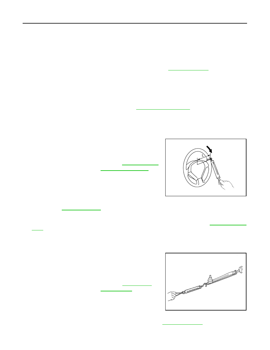
5.

Check steering wheel turning force when steering wheel has
been turned 540

°

 from neutral position.

NOTE:
Multiply the distance (L) from the hook of spring balance to the
center of steering wheel by the measurement value with a spring
balance.

6.

If steering wheel turning force is out of the specification, check
rack sliding force and relief hydraulic pressure of oil pump. Regarding relief hydraulic pressure of oil
pump, refer to 

ST-62, "Inspection"

.

RACK SLIDING FORCE

1.

Disconnect lower joint and steering knuckle from steering gear assembly. Refer to 

ST-43, "Exploded

View"

.

2.

Start and run the engine at idle to make sure steering fluid has reached normal operating temperature.

3.

While pulling outer socket slowly in 

±

11.5 mm (

±

0.453 in) range

from neutral position, make sure rack sliding force is within
specification.

4.

If rack sliding force is not within specification, overhaul steering
gear assembly.

FRONT WHEEL TURNING ANGLE

1.

Check front wheel turning angle after toe-in inspection. Refer to 

FSU-7, "Inspection"

.

Fluid temperature

: 50 – 80

°

C (122 – 176

°

F)

Standard

Steering wheel turning 
force

: Refer to 

ST-67, "Steering 

Wheel Turning Force"

.

JSGIA0027ZZ

Fluid temperature

: 50 – 80

°

C (122 – 176

°

F)

Standard

Rack sliding force

: Refer to 

ST-68, "Rack 

Sliding Force"

.

SST090B

STEERING WHEEL

ST-15

< BASIC INSPECTION >

[WITH HEATED STEERING WHEEL]

C

D

E

F

H

I

J

K

L

M

A

B

ST

N

O

P

2.

Place front wheels on turning radius gauges and rear wheels on
stands, so that vehicle can be level.

3.

Check the maximum inner and outer wheel turning angles for LH
and RH road wheels.

4.

With the engine at idle, turn steering wheel from full left stop to
full right stop and measure the turning angles.

5.

Check the following items when turning angle is out of the stan-
dard.

a.

Check the neutral position of the rack stroke (L).

b.

Disassemble steering gear assembly to check the cause that
rack stroke is outside of the standard.
• Steering angles are not adjustable. Check steering gear

assembly, steering column assembly and front suspension
components for wear or damage if any of the turning angles are different from the specified value.
Replace any of them, if any non-standard condition exists.

FAA0016D

Standard

Inner wheel (Angle: A)

: Refer to 

ST-67, "Steering 

Angle"

.

Outer wheel (Angle: B)

: Refer to 

ST-67, "Steering 

Angle"

.

SGIA0055E

Standard

Rack stroke neutral position (L)

: Refer to 

ST-68, 

"Rack Stroke"

.

SGIA0629J

ST-16

< DTC/CIRCUIT DIAGNOSIS >

[WITH HEATED STEERING WHEEL]

HEATED STEERING WHEEL SYSTEM

DTC/CIRCUIT DIAGNOSIS

HEATED STEERING WHEEL SYSTEM

Component Function Check

INFOID:0000000009721465

1.

CHECK HEATED STEERING WHEEL SYSTEM

Check operate heated steering wheel system. Refer to 

ST-10, "System Description (Heated Steering Wheel)"

.

Is the inspection result normal?

YES

>> Go to 

ST-16, "Diagnosis Procedure"

.

NO

>> INSPECTION END

Diagnosis Procedure

INFOID:0000000009721466

1.

CHECK POWER SOURCE AND GROUND CIRCUIT

1.

Turn ignition switch OFF.

2.

Remove the heated steering wheel. Refer to 

ST-36, "Removal and Installation"

.

3.

Turn ignition switch ON.

CAUTION:

Never start the engine.

4.

Turn heated steering wheel switch ON.

5.

Check voltage between heated steering wheel harness connector terminals.

Is the inspection result normal?

YES

>> GO TO 2.

NO

>> GO TO 3.

2.

CHECK HEATED STEERING WHEEL

Check heated steering wheel. Refer to 

ST-18, "Component Inspection (Heated Steering Wheel)"

.

Is the inspection result normal?

YES

>> INSPECTION END

NO

>> Replace heated steering wheel. Refer to 

ST-36, "Removal and Installation"

.

3.

CHECK GROUND CIRCUIT

Check continuity between heated steering wheel harness connector terminal and ground.

Is the inspection result normal?

YES

>> GO TO 4.

NO

>> Repair or replace damaged parts.

4.

CHECK HARNESS BETWEEN HEATED STEERING WHEEL RELAY AND HEATED STEERING WHEEL

1.

Turn ignition switch OFF.

2.

Disconnect heated steering wheel relay connector. Refer to 

ST-9, "Component Parts Location (Heated

Steering Wheel)"

.

3.

Disconnect heated steering wheel switch connector. Refer to 

ST-66, "Removal and Installation"

.

4.

Check continuity between heated steering wheel relay harness connector terminal and heated steering
wheel harness connector terminal.

Heated steering wheel

Condition

Voltage (Approx.)

Connector

Terminal

M309

 2

Within 30 minutes after 
turning ON the heated 
steering switch.

Battery voltage

Other conditions.

0 V

Heated steering wheel

Ground

Continuity

Connector

Terminal

M309

2

Existed

HEATED STEERING WHEEL SYSTEM

ST-17

< DTC/CIRCUIT DIAGNOSIS >

[WITH HEATED STEERING WHEEL]

C

D

E

F

H

I

J

K

L

M

A

B

ST

N

O

P

5.

Check continuity between heated steering wheel relay harness connector terminal and ground.

Is the inspection result normal?

YES

>> GO TO 5.

NO

>> Repair or replace damaged parts.

5.

CHECK HEATED STEERING WHEEL RELAY

Check heated steering wheel relay. Refer to 

ST-19, "Component Inspection (Heated Steering Wheel Relay)"

.

Is the inspection result normal?

YES

>> GO TO 6.

NO

>> Replace heated steering wheel relay. Refer to 

ST-9, "Component Parts Location (Heated Steering

Wheel)"

.

6.

CHECK POWER SUPPLY (BATTERY)

Check the following.
• Battery
• Harness for short or open between battery and 15 A fuse (No.26).
• 15 A fuse (No.26).
• Harness for short or open between 15 A fuse (No.26) and heated steering wheel relay.
Is the inspection result normal?

YES

>> GO TO 7.

NO

>> Repair or replace damaged parts.

7.

CHECK GROUND CIRCUIT

Check continuity between heated steering wheel switch harness connector terminal and ground.

Is the inspection result normal?

YES

>> GO TO 8.

NO

>> Repair or replace damaged parts.

8.

CHECK HARNESS BETWEEN HEATED STEERING WHEEL RELAY AND HEATED STEERING WHEEL

SWITCH

1.

Check continuity between heated steering wheel relay harness connector terminal and heated steering
wheel switch harness connector terminal.

2.

Check continuity between heated steering wheel relay harness connector terminal and ground.

Heated steering wheel relay

Heated steering wheel

Continuity

Connector

Terminal

Connector

Terminal

M27

5

M309

1

Existed

7

Heated steering wheel relay

Ground

Continuity

Connector

Terminal

M27

5

Not existed

7

Heated steering wheel switch

Ground

Continuity

Connector

Terminal

M28

6

Existed

Heated steering wheel relay

Heated steering wheel switch

Continuity

Connector

Terminal

Connector

Terminal

M27

2

M28

2

Existed


содержание   ..  1328  1329  1330  1331   ..