Nissan Murano. Manual - part 1239


  Главная      Nissan     Nissan Murano (2014 year) - Service Manual


поиск по сайту            


содержание   ..  1237  1238  1239  1240   ..


Nissan Murano. Manual - part 1239


B2556 PUSH-BUTTON IGNITION SWITCH

SEC-53

< DTC/CIRCUIT DIAGNOSIS >

[WITH INTELLIGENT KEY SYSTEM]

C

D

E

F

G

H

I

J

L

M

A

B

SEC

N

O

P

YES

>> Replace BCM. Refer to 

BCS-98, "Removal and Installation"

.

NO

>> Repair or replace harness or connector.

3.

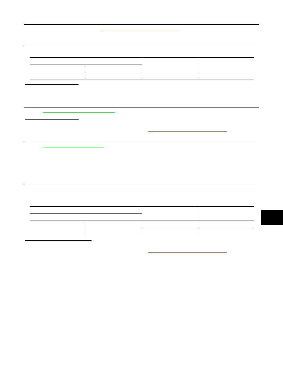
CHECK PUSH-BUTTON IGNITION SWITCH GROUND CIRCUIT

Check continuity between push-button ignition switch harness connector and ground.

Is the inspection normal?

YES

>> GO TO 4.

NO

>> Repair or replace harness or connector.

4.

CHECK PUSH-BUTTON IGNITION SWITCH

Refer to 

SEC-53, "Component Inspection"

.

Is the inspection normal?

YES

>> GO TO 5.

NO

>> Replace push-button ignition switch. Refer to 

SEC-191, "Removal and Installation"

.

5.

CHECK INTERMITTENT INCIDENT

Refer to 

GI-44, "Intermittent Incident"

.

>> INSPECTION END

Component Inspection

INFOID:0000000009722757

1.

CHECK PUSH-BUTTON IGNITION SWITCH

1.

Turn ignition switch OFF.

2.

Disconnect push-button ignition switch connector.

3.

Check continuity between push-button ignition switch terminals.

Is the inspection result normal?

YES

>> INSPECTION END

NO

>> Replace push-button ignition switch. Refer to 

SEC-191, "Removal and Installation"

.

Push-button ignition switch

Ground

Continuity

Connector

Terminal

M101

1

Existed

Push-button ignition switch

Condition

Continuity

Terminals

1

4

Pressed

Existed

Not pressed

Not existed

SEC-54

< DTC/CIRCUIT DIAGNOSIS >

[WITH INTELLIGENT KEY SYSTEM]

B2557 VEHICLE SPEED

B2557 VEHICLE SPEED

Description

INFOID:0000000009722758

BCM receives the 2 vehicle speed signals via CAN communication. 1 signal is transmitted by the combination
meter. Another signal is transmitted by “ABS actuator and electric unit (control unit)”. BCM compares both sig-
nals to detect the vehicle speed.

DTC Logic

INFOID:0000000009722759

DTC DETECTION LOGIC

NOTE:
• If DTC B2557 is displayed with DTC U1000, first perform the trouble diagnosis for DTC U1000. Refer to

SEC-31, "BCM : DTC Logic"

.

• If DTC B2557 is displayed with DTC U1010, first perform the trouble diagnosis for DTC U1010. Refer to

SEC-33, "BCM : DTC Logic"

.

DTC CONFIRMATION PROCEDURE

1.

PERFORM DTC CONFIRMATION PROCEDURE

1.

Drive the vehicle at the vehicle speed of 10 km/h (6.2 MPH) or more for at least 10 seconds.

2.

Check “Self diagnostic result” with CONSULT.

Is DTC detected?

YES

>> Go to 

SEC-54, "Diagnosis Procedure"

.

NO

>> INSPECTION END

Diagnosis Procedure

INFOID:0000000009722760

1.

CHECK DTC WITH “ABS ACTUATOR AND ELECTRIC UNIT (CONTROL UNIT)”

Check “Self diagnostic result” with CONSULT. Refer to 

BRC-111, "DTC No. Index"

.

Is the inspection result normal?

YES

>> GO TO 2.

NO

>> Repair or replace the malfunctioning parts.

2.

CHECK DTC WITH COMBINATION METER

Check “Self diagnostic result” with CONSULT. Refer to 

MWI-77, "DTC Index"

.

Is the inspection result normal?

YES

>> GO TO 3.

NO

>> Repair or replace the malfunctioning parts.

3.

CHECK INTERMITTENT INCIDENT

Refer to 

GI-44, "Intermittent Incident"

.

>> INSPECTION END

DTC

Self-diagnosis name

DTC detecting condition

Possible causes

B2557

VEHICLE SPEED

BCM detects the following difference between the vehicle 
speed from combination meter and the one from “ABS 
actuator and electric unit (control unit)” for 10 seconds 
continuously
• One is 10 km/h (6.2 MPH) or more and the other is 4 

km/h (2.5 MPH) or less.

• Wheel sensor
• Combination meter
• ABS actuator and electric unit 

(control unit)

B2560 STARTER CONTROL RELAY

SEC-55

< DTC/CIRCUIT DIAGNOSIS >

[WITH INTELLIGENT KEY SYSTEM]

C

D

E

F

G

H

I

J

L

M

A

B

SEC

N

O

P

B2560 STARTER CONTROL RELAY

Description

INFOID:0000000009722761

Starter control relay, integrated in IPDM E/R, permits the starter relay operation when in N or P position and
the steering is locked or unlocked (models with steering lock unit). It is installed in parallel with the starter relay.

DTC Logic

INFOID:0000000009722762

DTC DETECTION LOGIC

NOTE:
• If DTC B2560 is displayed with DTC U1000, first perform the trouble diagnosis for DTC U1000. Refer to

SEC-31, "BCM : DTC Logic"

.

• If DTC B2560 is displayed with DTC U1010, first perform the trouble diagnosis for DTC U1010. Refer to

SEC-33, "BCM : DTC Logic"

.

DTC CONFIRMATION PROCEDURE

1.

PERFORM DTC CONFIRMATION PROCEDURE

1.

Turn ignition switch ON under the following conditions and wait for at least 2 seconds.

-

Selector lever is in the P or N position.

-

Do not depress brake pedal.

2.

Check “Self diagnostic result” with CONSULT.

Is DTC detected?

YES

>> Go to 

SEC-55, "Diagnosis Procedure"

.

NO

>> INSPECTION END

Diagnosis Procedure

INFOID:0000000009722763

1.

CHECK DTC WITH IPDM E/R

Check “Self diagnostic result” with CONSULT. Refer to 

PCS-34, "DTC Index"

.

Is the inspection result normal?

YES

>> GO TO 2.

NO

>> Replace IPDM E/R. Refer to 

PCS-37, "Removal and Installation"

.

2.

CHECK INTERMITTENT INCIDENT

Refer to 

GI-44, "Intermittent Incident"

>> INSPECTION END

DTC

Self-diagnosis name

DTC detecting condition

Possible causes

B2560

STARTER CONT RELAY

BCM detects a mismatch between the OFF re-
quest of starter control relay to IPDM E/R and the 
feedback. (The feedback is ON instead of OFF.)

IPDM E/R

SEC-56

< DTC/CIRCUIT DIAGNOSIS >

[WITH INTELLIGENT KEY SYSTEM]

B2601 SHIFT POSITION

B2601 SHIFT POSITION

Description

INFOID:0000000009722764

BCM confirms the shift position with the following 4 signals.
• CVT shift selector (detention switch)
• Transmission range switch
• P position signal from IPDM E/R (CAN)
• P position signal from TCM (CAN)

DTC Logic

INFOID:0000000009722765

DTC DETECTION LOGIC

NOTE:
• If DTC B2601 is displayed with DTC U1000, first perform the trouble diagnosis for DTC U1000. Refer to

SEC-31, "BCM : DTC Logic"

.

• If DTC B2601 is displayed with DTC U1010, first perform the trouble diagnosis for DTC U1010. Refer to

SEC-33, "BCM : DTC Logic"

.

• If DTC B2601 is displayed with DTC B2603, first perform the trouble diagnosis for DTC B2603. Refer to

SEC-66, "DTC Logic"

.

DTC CONFIRMATION PROCEDURE

1.

PERFORM DTC CONFIRMATION PROCEDURE

1.

Turn ignition switch ON under the following conditions, and wait for at least 2 seconds.

-

Selector lever is in the P position.

-

Do not depress the brake pedal.

2.

Check “Self diagnostic result” with CONSULT.

Is DTC detected?

YES

>> Go to 

SEC-56, "Diagnosis Procedure"

.

NO

>> INSPECTION END

Diagnosis Procedure

INFOID:0000000009722766

1.

CHECK CVT SHIFT SELECTOR POWER SUPPLY

1.

Turn ignition switch OFF.

2.

Disconnect CVT shift selector (detention switch) connector.

3.

Check voltage between CVT shift selector (detention switch) harness connector and ground.

Is the inspection result normal?

YES

>> GO TO 3.

NO

>> GO TO 2.

2.

CHECK CVT SHIFT SELECTOR POWER SUPPLY CIRCUIT

1.

Disconnect BCM connector.

2.

Check continuity between CVT shift selector (detention switch) harness connector and BCM harness con-
nector.

DTC No.

Trouble diagnosis 

name

DTC detecting condition

Possible cause

B2601

SHIFT POSITION

BCM detects when a difference between the shift 
P input signal and the shift position signal re-
ceived from IPDM E/R via CAN communication 
continues for 2 seconds or more

• Harness or connectors

(CVT shift selector circuit is open or 
shorted.)

• CVT shift selector (detention switch)

(+)

(–)

Voltage (V)

(Approx.)

CVT shift selector (detention switch)

Connector

Terminal

M57

8

Ground

Battery voltage


содержание   ..  1237  1238  1239  1240   ..